Super User
IEC-101 to Modbus TCP Gateway
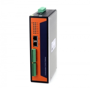
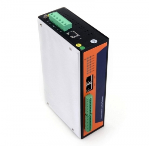
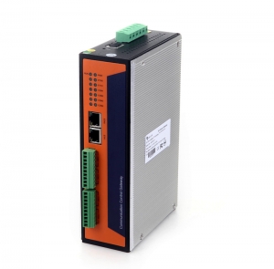
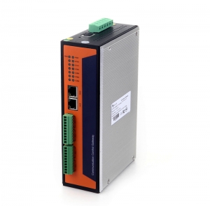
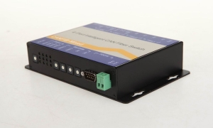
IEC-60870-5-101 Modbus Gateway
BUE-801A series IEC-60870-5 Gateways can provides both industrial communication device and solution of the whole industrial automation system,which plays more important roles in industrial control and automation,especially in the substation automation.The IEC-60870-5 sub protocols can communicate with each other,eg. The BUE-801A supports IEC-101 to IEC-102,IEC-101 to IEC-103,IEC-101 to IEC-104,IEC-102 to IEC-103,IEC-102 to IEC-104,IEC-103 to IEC-104, IEC-101 to Modbus RTU/TCP,IEC-102 to Modbus RTU/TCP,IEC-103 to Modbus RTU/TCP, IEC-104 to Modbus RTU/TCP and IEC-101/102/103/104 to IEC-61850 and other substation communication protocols.
1.Communication function:
Protocol conversion:
Standard protocols that BUE-801A support: UCA2,OPC,TCP/IP, Serial, DNP3,OPC, Modbus RTU/TCP, IEC60870-5 series(IEC101,IEC102,IEC103,IEC104), IEC61850.
Non-standard protocol: DC screen,power meter,safety equipments.The different protocols of data can convert with each other in the BUE-801A
Data processing:
Digital processing: signal acquisition & transmission,anti-shake,singnal maintenance, timing alarm, quality judgment.
Analog processing: multiplication coefficient, residual cleared, anti-mutation, quality judgment,etc.
Point table custom and information split:
In the BUE-801A system it provides different data forwarding point tables,different channels’ protocol can forward and each uses different data forwarding table. The same data can be submitted to the upper machine in the form of different value.
Dual channel processing:
BUE-801A Supports the system with dual channel mode and the upper machine communication, including fully redundant dual channel way, communication link redundancy, main equipment and so on.
Measuring point self description:
BUE-801A supports self description of data point, which is convenient for maintenance and debugging.
2.Advanced application:
Data calculation:
BUE-801A provides standard calculation formula and take the processing of data in the way of addition, subtraction, multiplication, division, logic judgment (including greater than, less than, equal to, is not equal to, greater than or equal to, less than or equal to, logic and logic, logic or, not), sine, cosine, square root, take maximum, minimum, average calculation.
Equipment automatic control can be set up:
BUE-801A provides the setting of basic control logic, timing or logical calculation according to the real-time data of on-site equipment start-stop switch quantity control and analog control, such as temperature, pressure, etc.
Advanced equipment control integration
3.Management function:
Debugging management:
BUE-801A provides all kinds of debugging methods and management, including remote debugging, intelligent device simulation, data simulation, control block, data browsing, message and debugging information monitoring, message storage and playback, flow rate and bit error rate statistics.
Equipment management:
Equipment management functions includes: remote diagnosis and maintenance, hardware watchdog, custom information indicator, main standby switch management etc.
Time synchronization:
BUE-801A can receive the time code from time servers,it can synchronizes time in the format of IRIG-B and NTP/SNTP.
4.System feature:
Low latency: 5 to 50ms latency.
Strong data processing ability.
Reliable communication management
5. Technical specifications:
Hardware:
10/100MTCP/IP: 2-6 nos
RS422/232/485 4-16 nos
DI/DO 8 nos
LED lights: 8nos
Wireless(GPRS/Zigbee/wifi/BD) 1 nos
Software:
Maximum channels:200
Maximum digital number/channel: 65536
Maximum analog number/channel: 65536
Maximum electric degree/channel: 65536
Maximum output/channel: 65536
Maximum analog output/channel: 65536
Data forwarding base: 4
Minimum data processing lantency: 5ms
Time synchronization precision:<1ms(Hardware synchronization)
Technical specs:
400Mhz Freescale MPC8308 CPU
128M DDR2 Memory
128M Nand Flash
2 Ethernet Ports
4 RS-232/485 Isolation Serial Ports
DIN-Rail Mount
|
System |
|
|
CPU |
Freescale MPC8308 PowerPC CPU,400MHz |
|
Memory |
DDR2 128M |
|
Flash |
8M Nor Flash |
|
128M Nand Flash |
|
|
Operating System |
Linux 2.6.29.6 |
|
LED |
|
|
System:Power x1,RUN x1, LAN:10/100/1000M x4(Link x2 Act x2) Serial:TxD x4,RxD x4 |
|
|
Others |
RTC,Buzzer,Watchdog Timer,Reset button,Console Port x1 |
|
Serial Communication |
|
|
Console Port |
Console Port RJ45 connector x1 RS232 115200bps N,8,1 |
|
Serial Port |
4 xRS-232/485 TB Interface connector software-selectable RS-232 Signals:TxD,RxD,GND RS-485 Signals:485A(Data+),485B(Data-) |
|
Protection |
Built-in 15KV ESD protection for all signals, 2KV iCoupler digital isolation protection |
|
Network Communication |
|
|
LAN |
Auto-sensing 10/100/1000Mbps x 2, RJ45 Build-in 1.5KV magnetic isolation protection |
|
Power Requirements |
|
|
Power Input |
Dual Power Input Design PWR1:9-48VDC or 9-48VAC PWR2:9-48VDC or 9-48VAC |
|
Lost power alarm |
Relay empty node |
|
Power Consumption |
|
|
8W@12VDC |
|
|
Mechanical |
|
|
Dimensions |
200(L)x121.01(W)x54.1(H) |
|
Installation |
DIN-Rail Mount |
|
Environmental |
|
|
Operating Temperature |
-20-60℃ |
|
Storage Temperature |
-30-80℃ |
|
Regulatory Approvals and Warranty |
|
|
EMC |
GB/T 17626.2-2006 Class 4 GB/T 17626.4-2008 Class 4 GB/T 17626.5-2008 Class 4 GB/T 17626.6-2008 Class 3 |
|
Warranty |
5 Years |
IEC-101 to IEC-104 Gateway
IEC-60870-5-101 to IEC-60870-5-104 Converter(Gateway)
BUE-801A series IEC-60870-5 Gateways can provides both industrial communication device and solution of the whole industrial automation system,which plays more important roles in industrial control and automation,especially in the substation automation.The IEC-60870-5 sub protocols can communicate with each other,eg. The BUE-801A supports IEC-101 to IEC-102,IEC-101 to IEC-103,IEC-101 to IEC-104,IEC-102 to IEC-103,IEC-102 to IEC-104,IEC-103 to IEC-104, IEC-101 to Modbus RTU/TCP,IEC-102 to Modbus RTU/TCP,IEC-103 to Modbus RTU/TCP, IEC-104 to Modbus RTU/TCP and IEC-101/102/103/104 to IEC-61850 and other substation communication protocols.
1.Communication function:
Protocol conversion:
Standard protocols that BUE-801A support: UCA2,OPC,TCP/IP, Serial, DNP3,OPC, Modbus RTU/TCP, IEC60870-5 series(IEC101,IEC102,IEC103,IEC104), IEC61850.
Non-standard protocol: DC screen,power meter,safety equipments.The different protocols of data can convert with each other in the BUE-801A
Data processing:
Digital processing: signal acquisition & transmission,anti-shake,singnal maintenance, timing alarm, quality judgment.
Analog processing: multiplication coefficient, residual cleared, anti-mutation, quality judgment,etc.
Point table custom and information split:
In the BUE-801A system it provides different data forwarding point tables,different channels’ protocol can forward and each uses different data forwarding table. The same data can be submitted to the upper machine in the form of different value.
Dual channel processing:
BUE-801A Supports the system with dual channel mode and the upper machine communication, including fully redundant dual channel way, communication link redundancy, main equipment and so on.
Measuring point self description:
BUE-801A supports self description of data point, which is convenient for maintenance and debugging.
2.Advanced application:
Data calculation:
BUE-801A provides standard calculation formula and take the processing of data in the way of addition, subtraction, multiplication, division, logic judgment (including greater than, less than, equal to, is not equal to, greater than or equal to, less than or equal to, logic and logic, logic or, not), sine, cosine, square root, take maximum, minimum, average calculation.
Equipment automatic control can be set up:
BUE-801A provides the setting of basic control logic, timing or logical calculation according to the real-time data of on-site equipment start-stop switch quantity control and analog control, such as temperature, pressure, etc.
Advanced equipment control integration
3.Management function:
Debugging management:
BUE-801A provides all kinds of debugging methods and management, including remote debugging, intelligent device simulation, data simulation, control block, data browsing, message and debugging information monitoring, message storage and playback, flow rate and bit error rate statistics.
Equipment management:
Equipment management functions includes: remote diagnosis and maintenance, hardware watchdog, custom information indicator, main standby switch management etc.
Time synchronization:
BUE-801A can receive the time code from time servers,it can synchronizes time in the format of IRIG-B and NTP/SNTP.
4.System feature:
Low latency: 5 to 50ms latency.
Strong data processing ability.
Reliable communication management
5. Technical specifications:
Hardware:
10/100MTCP/IP: 2-6 nos
RS422/232/485 4-16 nos
DI/DO 8 nos
LED lights: 8nos
Wireless(GPRS/Zigbee/wifi/BD) 1 nos
Software:
Maximum channels:200
Maximum digital number/channel: 65536
Maximum analog number/channel: 65536
Maximum electric degree/channel: 65536
Maximum output/channel: 65536
Maximum analog output/channel: 65536
Data forwarding base: 4
Minimum data processing lantency: 5ms
Time synchronization precision:<1ms(Hardware synchronization)
Technical specs:
400Mhz Freescale MPC8308 CPU
128M DDR2 Memory
128M Nand Flash
2 Ethernet Ports
4 RS-232/485 Isolation Serial Ports
DIN-Rail Mount
|
System |
|
|
CPU |
Freescale MPC8308 PowerPC CPU,400MHz |
|
Memory |
DDR2 128M |
|
Flash |
8M Nor Flash |
|
128M Nand Flash |
|
|
Operating System |
Linux 2.6.29.6 |
|
LED |
|
|
System:Power x1,RUN x1, LAN:10/100/1000M x4(Link x2 Act x2) Serial:TxD x4,RxD x4 |
|
|
Others |
RTC,Buzzer,Watchdog Timer,Reset button,Console Port x1 |
|
Serial Communication |
|
|
Console Port |
Console Port RJ45 connector x1 RS232 115200bps N,8,1 |
|
Serial Port |
4 xRS-232/485 TB Interface connector software-selectable RS-232 Signals:TxD,RxD,GND RS-485 Signals:485A(Data+),485B(Data-) |
|
Protection |
Built-in 15KV ESD protection for all signals, 2KV iCoupler digital isolation protection |
|
Network Communication |
|
|
LAN |
Auto-sensing 10/100/1000Mbps x 2, RJ45 Build-in 1.5KV magnetic isolation protection |
|
Power Requirements |
|
|
Power Input |
Dual Power Input Design PWR1:9-48VDC or 9-48VAC PWR2:9-48VDC or 9-48VAC |
|
Lost power alarm |
Relay empty node |
|
Power Consumption |
|
|
8W@12VDC |
|
|
Mechanical |
|
|
Dimensions |
200(L)x121.01(W)x54.1(H) |
|
Installation |
DIN-Rail Mount |
|
Environmental |
|
|
Operating Temperature |
-20-60℃ |
|
Storage Temperature |
-30-80℃ |
|
Regulatory Approvals and Warranty |
|
|
EMC |
GB/T 17626.2-2006 Class 4 GB/T 17626.4-2008 Class 4 GB/T 17626.5-2008 Class 4 GB/T 17626.6-2008 Class 3 |
|
Warranty |
5 Years |
IEC-104 to IEC-61850 Gateway
IEC-60870-5-104(IEC104) to IEC-61850 Gateway
BUE-801B series IEC-61850 Gateways can provides both industrial communication device and solution of the whole industrial automation system,which plays more important roles in industrial control and automation,especially in the substation automation.
Communication function:
Protocol conversion:
Standard protocols that BUE-801B support: UCA2,OPC,TCP/IP, Serial, DNP3,OPC, Modbus RTU/TCP, IEC60870-5 series(IEC101,IEC102,IEC103,IEC104), IEC61850.
Non-standard protocol: DC screen,power meter,safety equipments.The different protocols of data can convert with each other in the BUE-801B
Data processing:
Digital processing: signal acquisition & transmission,anti-shake,singnal maintenance, timing alarm, quality judgment.
Analog processing: multiplication coefficient, residual cleared, anti-mutation, quality judgment,etc.
Point table custom and information split:
In the BUE-801B IEC-61850 conversion gateway system it provides different data forwarding point tables,different channels’ protocol can forward and each uses different data forwarding table. The same data can be submitted to the upper machine in the form of different value.
Dual channel processing:
BUE-801B Supports the system with dual channel mode and the upper machine communication, including fully redundant dual channel way, communication link redundancy, main equipment and so on.
Measuring point self description:
BUE-801B supports self description of data point, which is convenient for maintenance and debugging.
Advanced application:
Data calculation:
BUE-801B provides standard calculation formula and take the processing of data in the way of addition, subtraction, multiplication, division, logic judgment (including greater than, less than, equal to, is not equal to, greater than or equal to, less than or equal to, logic and logic, logic or, not), sine, cosine, square root, take maximum, minimum, average calculation.
Equipment automatic control can be set up:
BUE-801B provides the setting of basic control logic, timing or logical calculation according to the real-time data of on-site equipment start-stop switch quantity control and analog control, such as temperature, pressure, etc.
Advanced equipment control integration
Management function:
Debugging management:
BUE-801B provides all kinds of debugging methods and management, including remote debugging, intelligent device simulation, data simulation, control block, data browsing, message and debugging information monitoring, message storage and playback, flow rate and bit error rate statistics.
Equipment management:
Equipment management functions includes: remote diagnosis and maintenance, hardware watchdog, custom information indicator, main standby switch management etc.
Time synchronization:
BUE-801B can receive the time code from time servers,it can synchronizes time in the format of IRIG-B and NTP/SNTP.
System feature:
Low latency: 5 to 50ms latency.
Strong data processing ability.
Reliable communication management
Technical specifications:
Hardware:
10/100MTCP/IP: 2-6 nos
RS422/232/485 4-16 nos
DI/DO 8 nos
LED lights: 8nos
Wireless(GPRS/Zigbee/wifi/BD) 1 nos
Software:
Maximum channels:200
Maximum digital number/channel: 65536
Maximum analog number/channel: 65536
Maximum electric degree/channel: 65536
Maximum output/channel: 65536
Maximum analog output/channel: 65536
Data forwarding base: 4
Minimum data processing lantency: 5ms
Time synchronization precision:<1ms(Hardware synchronization)
Technical specs:
400Mhz Freescale MPC8308 CPU
128M DDR2 Memory
128M Nand Flash
2 Ethernet Ports
4 RS-232/485 Isolation Serial Ports
DIN-Rail Mount
|
System |
|
|
CPU |
Freescale MPC8308 PowerPC CPU,400MHz |
|
Memory |
DDR2 128M |
|
Flash |
8M Nor Flash |
|
128M Nand Flash |
|
|
Operating System |
Linux 2.6.29.6 |
|
LED |
|
|
System:Power x1,RUN x1, LAN:10/100/1000M x4(Link x2 Act x2) Serial:TxD x4,RxD x4 |
|
|
Others |
RTC,Buzzer,Watchdog Timer,Reset button,Console Port x1 |
|
Serial Communication |
|
|
Console Port |
Console Port RJ45 connector x1 RS232 115200bps N,8,1 |
|
Serial Port |
4 xRS-232/485 TB Interface connector software-selectable RS-232 Signals:TxD,RxD,GND RS-485 Signals:485A(Data+),485B(Data-) |
|
Protection |
Built-in 15KV ESD protection for all signals, 2KV iCoupler digital isolation protection |
|
Network Communication |
|
|
LAN |
Auto-sensing 10/100/1000Mbps x 2, RJ45 Build-in 1.5KV magnetic isolation protection |
|
Power Requirements |
|
|
Power Input |
Dual Power Input Design PWR1:9-48VDC or 9-48VAC PWR2:9-48VDC or 9-48VAC |
|
Lost power alarm |
Relay empty node |
|
Power Consumption |
|
|
8W@12VDC |
|
|
Mechanical |
|
|
Dimensions |
200(L)x121.01(W)x54.1(H) |
|
Installation |
DIN-Rail Mount |
|
Environmental |
|
|
Operating Temperature |
-20-60℃ |
|
Storage Temperature |
-30-80℃ |
|
Regulatory Approvals and Warranty |
|
|
EMC |
GB/T 17626.2-2006 Class 4 GB/T 17626.4-2008 Class 4 GB/T 17626.5-2008 Class 4 GB/T 17626.6-2008 Class 3 |
|
Warranty |
5 Years |
IEC-101 to IEC-61850 Gateway
IEC-101(IEC-60870-5-101) to IEC61850 Gateway
BUE-801B series IEC101 to IEC-61850 Gateways can provides both industrial communication device and solution of the whole industrial automation system,which plays more important roles in industrial control and automation,especially in the substation automation.
Communication function:
Protocol conversion:
Standard protocols that BUE-801B support: UCA2,OPC,TCP/IP, Serial, DNP3,OPC, Modbus RTU/TCP, IEC60870-5 series(IEC101,IEC102,IEC103,IEC104), IEC61850.
Non-standard protocol: DC screen,power meter,safety equipments.The different protocols of data can convert with each other in the BUE-801B
Data processing:
Digital processing: signal acquisition & transmission,anti-shake,singnal maintenance, timing alarm, quality judgment.
Analog processing: multiplication coefficient, residual cleared, anti-mutation, quality judgment,etc.
Point table custom and information split:
In the BUE-801B system it provides different data forwarding point tables,different channels’ protocol can forward and each uses different data forwarding table. The same data can be submitted to the upper machine in the form of different value.
Dual channel processing:
BUE-801B Supports the system with dual channel mode and the upper machine communication, including fully redundant dual channel way, communication link redundancy, main equipment and so on.
Measuring point self description:
BUE-801B supports self description of data point, which is convenient for maintenance and debugging.
Advanced application:
Data calculation:
BUE-801B provides standard calculation formula and take the processing of data in the way of addition, subtraction, multiplication, division, logic judgment (including greater than, less than, equal to, is not equal to, greater than or equal to, less than or equal to, logic and logic, logic or, not), sine, cosine, square root, take maximum, minimum, average calculation.
Equipment automatic control can be set up:
BUE-801B provides the setting of basic control logic, timing or logical calculation according to the real-time data of on-site equipment start-stop switch quantity control and analog control, such as temperature, pressure, etc.
Advanced equipment control integration
Management function:
Debugging management:
BUE-801B provides all kinds of debugging methods and management, including remote debugging, intelligent device simulation, data simulation, control block, data browsing, message and debugging information monitoring, message storage and playback, flow rate and bit error rate statistics.
Equipment management:
Equipment management functions includes: remote diagnosis and maintenance, hardware watchdog, custom information indicator, main standby switch management etc.
Time synchronization:
BUE-801B can receive the time code from time servers,it can synchronizes time in the format of IRIG-B and NTP/SNTP.
System feature:
Low latency: 5 to 50ms latency.
Strong data processing ability.
Reliable communication management
Technical specifications:
Hardware:
10/100MTCP/IP: 2-6 nos
RS422/232/485 4-16 nos
DI/DO 8 nos
LED lights: 8nos
Wireless(GPRS/Zigbee/wifi/BD) 1 nos
Software:
Maximum channels:200
Maximum digital number/channel: 65536
Maximum analog number/channel: 65536
Maximum electric degree/channel: 65536
Maximum output/channel: 65536
Maximum analog output/channel: 65536
Data forwarding base: 4
Minimum data processing lantency: 5ms
Time synchronization precision:<1ms(Hardware synchronization)
Technical specs:
400Mhz Freescale MPC8308 CPU
128M DDR2 Memory
128M Nand Flash
2 Ethernet Ports
4 RS-232/485 Isolation Serial Ports
DIN-Rail Mount
|
System |
|
|
CPU |
Freescale MPC8308 PowerPC CPU,400MHz |
|
Memory |
DDR2 128M |
|
Flash |
8M Nor Flash |
|
128M Nand Flash |
|
|
Operating System |
Linux 2.6.29.6 |
|
LED |
|
|
System:Power x1,RUN x1, LAN:10/100/1000M x4(Link x2 Act x2) Serial:TxD x4,RxD x4 |
|
|
Others |
RTC,Buzzer,Watchdog Timer,Reset button,Console Port x1 |
|
Serial Communication |
|
|
Console Port |
Console Port RJ45 connector x1 RS232 115200bps N,8,1 |
|
Serial Port |
4 xRS-232/485 TB Interface connector software-selectable RS-232 Signals:TxD,RxD,GND RS-485 Signals:485A(Data+),485B(Data-) |
|
Protection |
Built-in 15KV ESD protection for all signals, 2KV iCoupler digital isolation protection |
|
Network Communication |
|
|
LAN |
Auto-sensing 10/100/1000Mbps x 2, RJ45 Build-in 1.5KV magnetic isolation protection |
|
Power Requirements |
|
|
Power Input |
Dual Power Input Design PWR1:9-48VDC or 9-48VAC PWR2:9-48VDC or 9-48VAC |
|
Lost power alarm |
Relay empty node |
|
Power Consumption |
|
|
8W@12VDC |
|
|
Mechanical |
|
|
Dimensions |
200(L)x121.01(W)x54.1(H) |
|
Installation |
DIN-Rail Mount |
|
Environmental |
|
|
Operating Temperature |
-20-60℃ |
|
Storage Temperature |
-30-80℃ |
|
Regulatory Approvals and Warranty |
|
|
EMC |
GB/T 17626.2-2006 Class 4 GB/T 17626.4-2008 Class 4 GB/T 17626.5-2008 Class 4 GB/T 17626.6-2008 Class 3 |
|
Warranty |
5 Years |
Modbus to IEC-61850 Gateway
Modbus RTU/TCP to IEC61850 Gateway
BUE-801B series Modbus to IEC-61850 Gateways can provides both industrial communication device and solution of the whole industrial automation system,which plays more important roles in industrial control and automation,especially in the substation automation.
1.Communication function:
Protocol conversion:
Standard protocols that BUE-801B support: UCA2,CDT,DLT645,TCP/IP, DNP3, OPC, Modbus RTU,Modbus TCP, IEC60870-5 series(IEC101,IEC102,IEC103,IEC104), IEC61850(Our IEC61850.
Non-standard protocol: DC screen,power meter,safety equipments.The different protocols of data can convert with each other in the BUE-801B
Data processing:
Digital processing: signal acquisition & transmission,anti-shake,singnal maintenance, timing alarm, quality judgment.
Analog processing: multiplication coefficient, residual cleared, anti-mutation, quality judgment,etc.
Point table custom and information split:
In the BUE-801B system it provides different data forwarding point tables,different channels’ protocol can forward and each uses different data forwarding table. The same data can be submitted to the upper machine in the form of different value.
Dual channel processing:
BUE-801B Supports the system with dual channel mode and the upper machine communication, including fully redundant dual channel way, communication link redundancy, main equipment and so on.
Measuring point self description:
BUE-801B supports self description of data point, which is convenient for maintenance and debugging.
Advanced application:Data calculation:
BUE-801B provides standard calculation formula and take the processing of data in the way of addition, subtraction, multiplication, division, logic judgment (including greater than, less than, equal to, is not equal to, greater than or equal to, less than or equal to, logic and logic, logic or, not), sine, cosine, square root, take maximum, minimum, average calculation.
Equipment automatic control can be set up:
BUE-801B provides the setting of basic control logic, timing or logical calculation according to the real-time data of on-site equipment start-stop switch quantity control and analog control, such as temperature, pressure, etc.
Advanced equipment control integration
Management function:
Debugging management:
BUE-801B provides all kinds of debugging methods and management, including remote debugging, intelligent device simulation, data simulation, control block, data browsing, message and debugging information monitoring, message storage and playback, flow rate and bit error rate statistics.
Equipment management:
Equipment management functions includes: remote diagnosis and maintenance, hardware watchdog, custom information indicator, main standby switch management etc.
Time synchronization:
BUE-801B can receive the time code from time servers,it can synchronizes time in the format of IRIG-B and NTP/SNTP.
System feature:
Low latency: 5 to 50ms latency.
Strong data processing ability.
Reliable communication management
Technical specifications:
Hardware:
10/100MTCP/IP: 2-6 nos
RS422/232/485 4-16 nos
DI/DO 8 nos
LED lights: 8nos
Wireless(GPRS/Zigbee/wifi/BD) 1 nos
Software:
Maximum channels:200
Maximum digital output number/channel: 65536
Maximum analog number/channel: 65536
Maximum electric degree/channel: 65536
Maximum output/channel: 65536
Maximum analog output/channel: 65536
Data forwarding base: 4
Minimum data processing lantency: 5ms
Time synchronization precision:<1ms(Hardware synchronization)
Technical specs:
400Mhz Freescale MPC8308 CPU
128M DDR2 Memory
128M Nand Flash
2 Ethernet Ports
4 RS-232/485 Isolation Serial Ports
DIN-Rail Mount
|
System |
|
|
CPU |
Freescale MPC8308 PowerPC CPU,400MHz |
|
Memory |
DDR2 128M |
|
Flash |
8M Nor Flash |
|
128M Nand Flash |
|
|
Operating System |
Linux 2.6.29.6 |
|
LED |
|
|
System:Power x1,RUN x1, LAN:10/100/1000M x4(Link x2 Act x2) Serial:TxD x4,RxD x4 |
|
|
Others |
RTC,Buzzer,Watchdog Timer,Reset button,Console Port x1 |
|
Serial Communication |
|
|
Console Port |
Console Port RJ45 connector x1 RS232 115200bps N,8,1 |
|
Serial Port |
4 xRS-232/485 TB Interface connector software-selectable RS-232 Signals:TxD,RxD,GND RS-485 Signals:485A(Data+),485B(Data-) |
|
Protection |
Built-in 15KV ESD protection for all signals, 2KV iCoupler digital isolation protection |
|
Network Communication |
|
|
LAN |
Auto-sensing 10/100/1000Mbps x 2, RJ45 Build-in 1.5KV magnetic isolation protection |
|
Power Requirements |
|
|
Power Input |
Dual Power Input Design PWR1:9-48VDC or 9-48VAC PWR2:9-48VDC or 9-48VAC |
|
Lost power alarm |
Relay empty node |
|
Power Consumption |
|
|
8W@12VDC |
|
|
Mechanical |
|
|
Dimensions |
200(L)x121.01(W)x54.1(H) |
|
Installation |
DIN-Rail Mount |
|
Environmental |
|
|
Operating Temperature |
-20-60℃ |
|
Storage Temperature |
-30-80℃ |
|
Regulatory Approvals and Warranty |
|
|
EMC |
GB/T 17626.2-2006 Class 4 GB/T 17626.4-2008 Class 4 GB/T 17626.5-2008 Class 4 GB/T 17626.6-2008 Class 3 |
|
Warranty |
5 Years |
CAN to Multi-drop Bus Fiber Optic Converter
Configurable CAN to Multi-drop Bus Fiber Optic(FO) Converter
Description:
The FO-FIB-100BT CAN bus to fiber optic switch provide an optical Multi-drop bus or star network connection for CAN bus data interfaces on one or two, multi mode or single mode optical fibers. The CAN bus fiber optic switch has 1 CAN port and 2 fiber optic ports, CAN port is configurable via software.The CAN bus series units support both CAN 1.0 and CAN 2.0B CAN standards and are transparent to all high level protocols.The converter adopts the latest technology int world, so it can support very high baud rate,very long distance,very complex networks.
Product Features and Benefits:
Up to 1Mbps data rate(20km when it’s 1MB,New technology)Up to 6500 frames/second,with 1000 frames bufferingConfigurable CAN bus InterfaceMulti mode and single modeWith bufferingSingle fiber solution supported5 years warranty
Other Specifications:
|
Data |
|
|
Data Formats |
CAN1.0 ,CAN2.0 ,Device Net |
|
CAN Data Rate |
0-1Mbps |
|
Bit Error Rate |
<1 x 10-12 |
|
Connectors |
|
|
Data |
Screw Block Terminal |
|
Fiber |
ST, SC or FC (ST fitted as standard) |
|
Environmental |
|
|
Operating Temperature |
-30C---+70C |
|
Storage Temperature |
-40C---+90C |
|
Operating Humidity |
0-95% |
|
MTBF |
>100,000 Hours |
|
Optical |
|
|
Fiber |
Multi mode or single mode |
|
Wavelength |
850nm/1310nm |
|
Number of fibers |
8 or 4(WDM,Bi-Di) (2TX+2RX) |
|
Power |
|
|
Power Input |
+9-+40V DC |
|
Mechanical |
|
|
Dimensions |
156(W)×108(D)×33.6(H)mm Wall mount |
Ordering Information:
|
Model Number |
Description |
Port No. |
Fiber Mode |
Fiber Connector |
|
HFD-FO-CAN-P1M |
Fiber Optic Converter,Point to Point Link, Single Fiber(BI-DI), 2km,DIN Rail Mount |
1 CAN +1 FO |
Multi Mode |
ST/SC/FC |
|
HFD-FO-CAN-P2M |
Fiber Optic Converter,Point to Point Link, Dual Fiber, 2km,DIN Rail Mount |
1 CAN+1TX+1RX |
Multi Mode |
ST/SC/FC |
|
HFD-FO-CAN-P1S |
Fiber Optic Converter,Point to Point Link, Single Fiber(BI-DI), 20km |
1 CAN +1 FO |
Single Mode |
ST/SC/FC |
|
HFD-FO-CAN-P2S |
Fiber Optic Converter,Point to Point Link, Dual Fiber, 20km |
1 CAN+1TX+1RX |
Single Mode |
ST/SC/FC |
|
FO-FIB-100PT |
Configurable Fiber Optic Converter, Point to Point Link,Wall Mount |
1CAN+1TX+1RX |
Single Mode |
ST/SC/FC |
|
FO-FIB-100BT |
Configurable Fiber Optic Converter, Multi Drop Link,Wall Mount |
1CAN+2TX+2RX |
Single Mode |
ST/SC/FC |
|
FO-FIB-MIXED |
Configurable CAN Fiber Optic Switch, Point to point,Multi-drop,Star,Tree, Wall Mount |
2 CAN+2TX+2RX |
Single Mode |
ST/SC/FC |
|
SW-400T |
4 Port Configurable CAN BUS Switch, Wall Mount |
4 CAN |
||
|
BRIGE-200T |
Configurable CAN TO CAN Bridge |
2 CAN |
||
|
CANET-I |
1 Port CAN to Ethernet Converter |
1 CAN+1 TCP |
||
|
CANET-II |
2 Port CAN to Ethernet Converter |
2 CAN+1 TCP |
||
|
CAN-USB-I |
1 Port CAN to USB Converter |
1 CAN+1 USB |
||
|
CAN-USB-II |
2 Port CAN to USB Converter |
2 CAN+1 USB |
||
|
CAN-PCI-5001 |
1 Port CAN PCI Card |
1 CAN+1 PCI |
||
|
CAN-PCI-5002 |
2 Port CAN PCI Card |
2 CAN+1 PCI |
||
|
CAN-232 |
CAN to RS-232 Converter |
1 CAN+1RS232 |
||
|
CAN-485 |
CAN to RS-485 Converter |
1 CAN+1RS485 |
CAN Fiber Optic Switch
CAN Bus Fiber Optic Switch(2 Port CAN+2 Port Optical)
Description:
The FO-FIB-MIXED Can bus to fiber optic switch provide an optical point-to-point or bus network connection for Can bus data interfaces on one or two, multimode or single mode optical fibers. The Canbus fiber optic switch has 2 CAN ports and 2 fiber optic ports, all 4 ports are configurable via software.Any port can communicate with other ports,so it has the functions of “Repeater”,”Router” and “Switch”, it can be used in point to point,multi drop bus,star and tree topologies. The Can bus series units support both CAN 1.0 and CAN 2.0B CAN standards and are transparent to all high level protocols.
Product Features and benefits:
•All CAN BUS Ports are configurable by software.
•CAN BUS ports can transmit data in different or same baud rate
•Up to 1Mbps data rate(20km when it’s 1MB,New technology)
•Up to 6500 frames/second, with 1000 frames buffering
•All ports can communicate with each other
•Multi mode and single mode
•Point to point,Multi-drop Bus,Star and Tree topologies
•Single fiber solution supported
•5 years warranty
Specifications:
| Data | |
| Data Formats | CAN1.0 ,CAN2.0 ,Device Net |
| CAN Data Rate | 0-1Mbps |
| Bit Error Rate | <1 x 10-12 |
| Connectors | |
| Data | Screw Block Terminal 2 ports |
| Fiber | ST, SC or FC (ST fitted as standard) |
| Environmental | |
| Operating Temperature | -30C---+70C |
| Storage Temperature | -40C---+90C |
| Operating Humidity | 0-95% |
| MTBF | >100,000 Hours |
| Optical | |
| Fiber | Multi mode or single mode |
| Wavelength | MM:850nm,SM:1310nm |
| Number of fibers | 8 or 4(WDM,Bi-Di) (2TX+2RX) |
| Power | |
| Power Input | +9-+40V DC |
| Mechanical | |
| Dimensions |
156(W)×108(D)×33.6(H)mm Wall mount |
Ordering Information:
| Model Number | Description | Port No. | Fiber Mode | Fiber Connector |
| HFD-FO-CAN-P1M |
Fiber Optic Converter,Point to Point Link, Single Fiber(BI-DI), 2km,DIN Rail Mount |
1 CAN +1 FO | Multi Mode | ST/SC/FC |
| HFD-FO-CAN-P2M |
Fiber Optic Converter,Point to Point Link, Dual Fiber, 2km,DIN Rail Mount |
1 CAN+1TX+1RX | Multi Mode | ST/SC/FC |
| HFD-FO-CAN-P1S |
Fiber Optic Converter,Point to Point Link, Single Fiber(BI-DI), 20km |
1 CAN +1 FO | Single Mode | ST/SC/FC |
| HFD-FO-CAN-P2S |
Fiber Optic Converter,Point to Point Link, Dual Fiber, 20km |
1 CAN+1TX+1RX | Single Mode | ST/SC/FC |
| FO-FIB-100PT |
Configurable Fiber Optic Converter, Point to Point Link,Wall Mount |
1CAN+1TX+1RX | SM/MM | ST/SC/FC |
| FO-FIB-100BT |
Configurable Fiber Optic Converter, Multi Drop Link,Wall Mount |
1CAN+2TX+2RX | SM/MM | ST/SC/FC |
| FO-FIB-MIXED |
Configurable CAN Fiber Optic Switch, Point to point,Multi-drop,Star,Tree, Wall Mount |
2 CAN+2TX+2RX | SM/MM | ST/SC/FC |
| SW-400T |
4 Port Configurable CAN BUS Switch, Wall Mount |
4 CAN | ||
| BRIGE-200T | Configurable CAN TO CAN Bridge | 2 CAN | ||
| CANET-I | 1 Port CAN to Ethernet Converter | 1 CAN+1 TCP | ||
| CANET-II | 2 Port CAN to Ethernet Converter | 2 CAN+1 TCP | ||
| CAN-USB-I | 1 Port CAN to USB Converter | 1 CAN+1 USB | ||
| CAN-USB-II | 2 Port CAN to USB Converter | 2 CAN+1 USB | ||
| CAN-PCI-5001 | 1 Port CAN PCI Card | 1 CAN+1 PCI | ||
| CAN-PCI-5002 | 2 Port CAN PCI Card | 2 CAN+1 PCI | ||
| CAN-232 | CAN to RS-232 Converter | 1 CAN+1RS232 | ||
| CAN-485 | CAN to RS-485 Converter | 1 CAN+1RS485 |
CAN Repeater
CAN Repeater
The BRIDGE-200T Series CAN Bus Isolated Repeater utilizes automatic bidirectional switching requiring no control signal. This product can insulate CAN bus for a distance up to 10Km. This product enables equipment connections to the bus to be doubled. All upper levels protocol is supported.It has software in it,so both CANbus sides' baud rate can be set up by software.
Feature & Benefits:
The CANbridge allows the coupling of two CAN networks, including networks with different baud rates. Unlike a CAN Repeater, which only translates the electric signals, the CAN messages are received completely by the CANbridge and then sent to the other CAN network in line with existing filter and conversion rules (Store-Forward principle). With the aid of conversion rules (gateway tables), CAN messages can be filtered or forwarded under another identifier. With these mechanisms, the bus load can be reduced in the individual networks by only sending messages which are of interest to the other network.
The Series CAN Bus Isolated Repeater can be widely used, such as Industrial Controls, Intelligent Transportation Systems (ITS), Industrial Networking,
Supervisory Control and Data (SCADA) and so on.
Other Specs:
Linking two CAN nets with data bufferingDifferent bit rates on the CAN nets possible11-bit ID and 29-bit ID bridgeInternal microcontroller MB90F543High-Speed CAN interface acc. to ISO 11898-2, 1 Mbit/sElectrical isolation by optocouplers and DC/DC-convertersConfiguration of the CAN-CBM-Bridge/2 module is easily done by means of a PC/terminalIsolation 3000VsmLightning/Surge Protection 1~2 lightning strikesESD Protection 15KV
CAN BUS:
Connector Type TerminalData Rate DC 0-1MbpsExtended Distance 10KmOperating Temperature -40 ~ 70C / -40 ~ +158FOperating Humidity 0 ~ 95% non-condensingMean Time Between Failure (MTBF) > 70, 000hrsPower Supply Input Voltage 9~40V DCPower Supply Output Voltage 5V DCDimensions (W × D× W) 156mm× 108mm× 33.6mm
Ordering Information:
|
Model Number |
Description |
Port No. |
Fiber Mode |
Fiber Connector |
|
HFD-FO-CAN-P1M |
Fiber Optic Converter,Point to Point Link, Single Fiber(BI-DI), 2km,DIN Rail Mount |
1 CAN +1 FO |
Multi Mode |
ST/SC/FC |
|
HFD-FO-CAN-P2M |
Fiber Optic Converter,Point to Point Link, Dual Fiber, 2km,DIN Rail Mount |
1 CAN+1TX+1RX |
Multi Mode |
ST/SC/FC |
|
HFD-FO-CAN-P1S |
Fiber Optic Converter,Point to Point Link, Single Fiber(BI-DI), 20km |
1 CAN +1 FO |
Single Mode |
ST/SC/FC |
|
HFD-FO-CAN-P2S |
Fiber Optic Converter,Point to Point Link, Dual Fiber, 20km |
1 CAN+1TX+1RX |
Single Mode |
ST/SC/FC |
|
FO-FIB-100PT |
Configurable Fiber Optic Converter, Point to Point Link,Wall Mount |
1CAN+1TX+1RX |
Single Mode |
ST/SC/FC |
|
FO-FIB-100BT |
Configurable Fiber Optic Converter, Multi Drop Link,Wall Mount |
1CAN+2TX+2RX |
Single Mode |
ST/SC/FC |
|
FO-FIB-MIXED |
Configurable CAN Fiber Optic Switch, Point to point,Multi-drop,Star,Tree, Wall Mount |
2 CAN+ FO(2TX+2RX) |
Single Mode |
ST/SC/FC |
|
SW-400T |
4 Port Configurable CAN BUS Switch, Wall Mount |
4 CAN |
||
|
BRIGE-200T |
Configurable CAN TO CAN Bridge |
2 CAN |
||
|
CANET-I |
1 Port CAN to Ethernet Converter |
1 CAN+1 TCP |
||
|
CANET-II |
2 Port CAN to Ethernet Converter |
2 CAN+1 TCP |
||
|
CAN-USB-I |
1 Port CAN to USB Converter |
1 CAN+1 USB |
||
|
CAN-USB-II |
2 Port CAN to USB Converter |
2 CAN+1 USB |
||
|
CAN-PCI-5001 |
1 Port CAN PCI Card |
1 CAN+1 PCI |
||
|
CAN-PCI-5002 |
2 Port CAN PCI Card |
2 CAN+1 PCI |
||
|
CAN-232 |
CAN to RS-232 Converter |
1 CAN+1RS232 |
||
|
CAN-485 |
CAN to RS-485 Converter |
1 CAN+1RS485 |
CAN Bus Router
4 Port Manageable CAN Switch(CAN Router)
Description of CAN Bus Switch:
The SW-400T CAN Bus Switch is a new CAN bus switch that combined the world's most advanced technology into it. There are 4 independent CAN channels who can communicate with each other with different or same baud rates. This new topology could resolve the complex CAN bus application, like industrial automation, building automation, Alarm System,ITS, and etc. The SW-400T CAN switch can run to 6000 to 6500 frames/second and it has buffering to ensure the reliability of the CAN data transmission. It helps users to extend the CAN network system. The SW-400T comes with configurable software and UART console port.
Product Features of CANbus Switch:
4 CAN bus ports(Configurable)Compatible with CAN specification 2.0A and 2.0BFully compatible with the ISO 11898-2 standardBaud rate : 0-1MB, Can be configured by softwareCAN bus filter is configurable1500 data frames buffer for each CAN channelMax data flow up to 6500 frames in totalSelectable baud rate by rotary switchSelectable 120Ω terminator resistor by DIP switchLED for CAN reception and transmissionSupport CAN network with star or tree topologyDifferent baud rates can communicate in the switch
Other Specifications of CAN Bus Switch:
Hardware
Controller High Performance Microcontroller
CAN Interface
CAN: 4 Ports Block terminal connector
CAN Standard: ISO-11898-2, CAN 2.0A and CAN 2.0B
Baud Rate (bps): 0-1MB
Baud Rate Setting up: By rotary switch
Isolation 3000 VDC for DC-to-DC, 2500 Vrms for photo-couple
Terminator Resistor Selectable 120Ω terminator resistor by internal jump
Transmission Distance (m) Depend on baud rate (for example, max. 1000 m at 50 kbps )
CAN Filter Configurable by user
Console Interface
RS-232 1 port (for configuration)
Power
Input range Unregulated +9 ~ +40 VDC
Power Consumption 1.5W
Mechanism
Installation Wall-Mounting
Casing Aluminum metallic case
Dimensions 156 x 108 x 33.6 mm (WxDxH)
Environment
Operating Temp. -30 ~ 80 ℃
Storage Temp. -35 ~ 90 ℃
Humidity 10 ~ 95% RH, non-condensing
ESD protection 10 kV Contact for each channel
EFT protection 500V for signal, 1000V for power
Application of the CAN Bus Switch:
ITS,Power automation,Industrial Automation,Fire Alarm System,Lift control,etc.
Ordering Information:
|
Model Number |
Description |
Port No. |
Fiber Mode |
Fiber Connector |
|
HFD-FO-CAN-P1M |
Fiber Optic Converter,Point to Point Link, Single Fiber(BI-DI), 2km,DIN Rail Mount |
1 CAN +1 FO |
Multi Mode |
ST/SC/FC |
|
HFD-FO-CAN-P2M |
Fiber Optic Converter,Point to Point Link, Dual Fiber, 2km,DIN Rail Mount |
1 CAN+1TX+1RX |
Multi Mode |
ST/SC/FC |
|
HFD-FO-CAN-P1S |
Fiber Optic Converter,Point to Point Link, Single Fiber(BI-DI), 20km |
1 CAN +1 FO |
Single Mode |
ST/SC/FC |
|
HFD-FO-CAN-P2S |
Fiber Optic Converter,Point to Point Link, Dual Fiber, 20km |
1 CAN+1TX+1RX |
Single Mode |
ST/SC/FC |
|
FO-FIB-100PT |
Configurable Fiber Optic Converter, Point to Point Link,Wall Mount |
1CAN+1TX+1RX |
Single Mode |
ST/SC/FC |
|
FO-FIB-100BT |
Configurable Fiber Optic Converter, Multi Drop Link,Wall Mount |
1CAN+2TX+2RX |
Single Mode |
ST/SC/FC |
|
FO-FIB-MIXED |
Configurable CAN Fiber Optic Switch, Point to point,Multi-drop,Star,Tree, Wall Mount |
2 CAN+(2TX+2RX) |
Single Mode |
ST/SC/FC |
|
SW-400T |
4 Port Configurable CAN BUS Switch, Wall Mount |
4 CAN |
||
|
BRIGE-200T |
Configurable CAN TO CAN Bridge |
2 CAN |
||
|
CANET-I |
1 Port CAN to Ethernet Converter |
1 CAN+1 TCP |
||
|
CANET-II |
2 Port CAN to Ethernet Converter |
2 CAN+1 TCP |
||
|
CAN-USB-I |
1 Port CAN to USB Converter |
1 CAN+1 USB |
||
|
CAN-USB-II |
2 Port CAN to USB Converter |
2 CAN+1 USB |
||
|
CAN-PCI-5001 |
1 Port CAN PCI Card |
1 CAN+1 PCI |
||
|
CAN-PCI-5002 |
2 Port CAN PCI Card |
2 CAN+1 PCI |
||
|
CAN-232 |
CAN to RS-232 Converter |
1 CAN+1RS232 |
||
|
CAN-485 |
CAN to RS-485 Converter |
1 CAN+1RS485 |
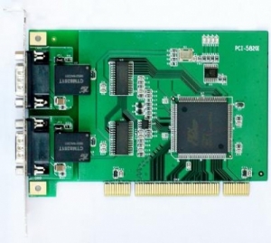
CAN PCI Card
One or 2 Channel Isolated CAN Bus PCI Interface Cards
Introduction:
The PCI-CAN card is a Controller Area Network (CAN) interface card. It supports one or dual-port CAN's interface that can run independently or bridged at the same time. The built-in CAN controller of this card is Philips SJA1000, which provides bus arbitration and error detection with auto correction and re-transmission function.
Features of Our CAN PCI Card:
- Passive CAN Interface for PCI slots
- One, two CAN channels with Controller NXP SJA1000
- Baud rates up to 1MBaud, 82C251 Transceiver
- CAN is connected via a 9-pin SUB-D as defined by the CiA DS102-1 standard
- CAN 2.0A (11-bit ID standard frames) and 2.0B (29-bit ID extended frames)
- Development kits for Windows 2000/XP/Vista
- Examples of Visual Basic 6.0, Visual C++ 6.0, C++builder 6.0, Delphi7.0, Labview are available
- Max data flow 3000 fps (extend frame)
- Operating temperature: -25 to +85C
Application of Our CAN PCI Card:
CAN-bus product development, CAN-bus data analyzer, CAN-bus master/slave network, CAN-bus Teaching applications,CAN-bus gateway/bridge,CAN-bus industrial control & automation,Smart building system, Data transfer between different CAN-bus networks.
Ordering Information:
|
Model Number |
Description |
Port No. |
Fiber Mode |
Fiber Connector |
|
HFD-FO-CAN-P1M |
Fiber Optic Converter,Point to Point Link, Single Fiber(BI-DI), 2km,DIN Rail Mount |
1 CAN +1 FO |
Multi Mode |
ST/SC/FC |
|
HFD-FO-CAN-P2M |
Fiber Optic Converter,Point to Point Link, Dual Fiber, 2km,DIN Rail Mount |
1 CAN+1TX+1RX |
Multi Mode |
ST/SC/FC |
|
HFD-FO-CAN-P1S |
Fiber Optic Converter,Point to Point Link, Single Fiber(BI-DI), 20km |
1 CAN +1 FO |
Single Mode |
ST/SC/FC |
|
HFD-FO-CAN-P2S |
Fiber Optic Converter,Point to Point Link, Dual Fiber, 20km |
1 CAN+1TX+1RX |
Single Mode |
ST/SC/FC |
|
FO-FIB-100PT |
Configurable Fiber Optic Converter, Point to Point Link,Wall Mount |
1CAN+1TX+1RX |
Single Mode |
ST/SC/FC |
|
FO-FIB-100BT |
Configurable Fiber Optic Converter, Multi Drop bus Link,Wall Mount |
1CAN+2TX+2RX |
Single Mode |
ST/SC/FC |
|
FO-FIB-MIXED |
Configurable CAN Fiber Optic Switch, Point to point,Multi-drop,Star,Tree, Wall Mount |
2CAN+FO(2TX+2RX) |
Single Mode |
ST/SC/FC |
|
SW-400T |
4 Port Configurable CAN BUS Switch, Wall Mount |
4 CAN |
||
|
BRIGE-200T |
Configurable CAN TO CAN Bridge |
2 CAN |
||
|
CANET-I |
1 Port CAN to Ethernet Converter |
1 CAN+1 TCP |
||
|
CANET-II |
2 Port CAN to Ethernet Converter |
2 CAN+1 TCP |
||
|
CAN-USB-I |
1 Port CAN to USB Converter |
1 CAN+1 USB |
||
|
CAN-USB-II |
2 Port CAN to USB Converter |
2 CAN+1 USB |
||
|
CAN-PCI-5001 |
1 Port CAN PCI Card |
1 CAN+1 PCI |
||
|
CAN-PCI-5002 |
2 Port CAN PCI Card |
2 CAN+1 PCI |
||
|
CAN-232 |
CAN to RS-232 Converter |
1 CAN+1RS232 |
||
|
CAN-485 |
CAN to RS-485 Converter |
1 CAN+1RS485 |

