
Super User
Rack Mount Gigabit Unmanaged Industrial Ethernet Switch
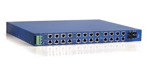
Rack Mount Gigabit Unmanaged Industrial Ethernet Switches
Overview:
* High Port Density, Up to 24 Fast-Ethernet Ports and 2 Gigabit Combo Ports
* Elastic configuration, 100Base fiber port with SC/ST connectors, multi-mode/single-mode models are available
* Multiple power inputs include low voltage redundant power models or 110/220VAC models
Specifications:
* Technology
Network Standards:
IEEE802.3 10Base-T
IEEE802.3u 100BaseT(X) and 100BaseFX
IEEE802.3ad 1000Base(X)
IEEE802.3z 1000BaseSX/LX/HLX/ZX
IEEE802.3x Flow Control
Flow Control:Full/Half Duplex Back Pressure Flow Control
* Interface
RJ45 Port Connectors:10/100Base(X) or 10/100/1000BaseT(X) Auto-Negotiation
Fiber Port Connectors:1000BaseSX/CX/LHX/ZX(SFP slots, LC connectors)
LED Indicators:Power, Port Status, 10/100/1000M
* Power Requirements
Power Inputs:48VDC(8~56VDC); 110/220VAC(85~265VDC);
220VDC(120~370VDC); 110VDC(100~120VDC);
* Fiber Optic:
| Mode | Typical Dist | Wavelength | Cable Size | TX Power | Rx Sensitivity | Transmission speed |
| Multi | 2km | 1310nm | 62.5/125um | -23.5~-14dBm | < -35dBm | 10/100/1000Mbps |
| Single | 15km | 1310nm | 9/125um | -15~-8dBm | < -35dBm | 10/100/1000Mbps |
* Physical Characteristics
Case:Slim Metal Case, IP40 Design
Dimensions:(W×H×D):443×44×220mm(HFB18C-2G/26C-2G)
Installation:19" rack mounting
* Environment Limits
Standard Temp Models:-10˚C to 60˚C
Extended Temp Models:-40˚C to 75˚C
Storage Temperature:-40 to 85℃
Ambient Relative Humidity: 10 to 95%(Non-condensing)
* Ordering Information
| Product Model | Connectors | ||||
| (-10℃~60℃) | (-40℃~75℃) | 10/100/ 1000BaseT(X) or 1000Base SFP |
10/100 BaseT(X) |
100BaseFX | |
| MM Fiber, SC | SM Fiber, SC | ||||
| HFB18C-2G Series | |||||
| HFB18C-2G | HFB18C-2G-W | 2 | 16 | ||
| HFB18C-2G-2SC | HFB18C-2G-2SC-W | 2 | 14 | 2 | |
| HFB18C-2G-2SSC | HFB18C-2G-2SSC-W | 2 | 14 | 2 | |
| HFB18C-2G-4SC | HFB18C-2G-4SC-W | 2 | 12 | 4 | |
| HFB18C-2G-4SSC | HFB18C-2G-4SSC-W | 2 | 12 | 4 | |
| HFB26C-2G Series | |||||
| HFB26C-2G | HFB26C-2G-W | 2 | 24 | ||
| HFB26C-2G-2SC | HFB26C-2G-2SC-W | 2 | 22 | 2 | |
| HFB26C-2G-2SSC | HFB26C-2G-2SSC-W | 2 | 22 | 2 | |
| HFB26C-2G-4SC | HFB26C-2G-4SC-W | 2 | 20 | 4 | |
| HFB26C-2G-4SSC | HFB26C-2G-4SSC-W | 2 | 20 | 4 | |
- All fiber cables can be equipped with ST or SC connectors
- Typical Distance:Multi mode<15km; Single mode: Ranging from 15km to 120km
- The standard models are powered by 24VDC, 110-220VAC/DC customized models are also available
Rack Mount Unmanaged Industrial Ethernet Switches
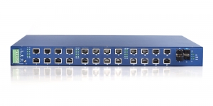
Rack Mount Unmanaged Industrial Ethernet Switches with 10/100M
Supports up to 8 Fiber optic Ports, Increase Flexibility,Ruggedized Industrial Grade Housing,Multiple power inputs include low voltage redundant power models and 110-220VAC/DC models,Broadcasting Storm Controller
Specifications:
Technology
Network Standards:
IEEE802.3 10Base-T
IEEE802.3u 100BaseT(X) and 100BaseFX
IEEE802.3x Flow Control
MAC Address:8K MAC Address Table
Flow Control:Full/Half Duplex Back Pressure Flow Control
Interface
RJ45 Port Connectors:10/100Base Auto-sensing, Full/Half Duplex MDI/MDI-X Auto-Negotiation
Fiber Port Connectors:100BaseFX, SC or ST connectors, Single-Mode or Multi-Mode
LED Indicators:Power, Port Status
Power Requirements
Power Inputs:48VDC(8~56VDC); 110/220VAC(85~265VDC);
220VDC(120~370VDC); 110VDC(100~120VDC);
Optical Fiber
| Mode | Typical Dist | Wavelength | Cable Size | TX Power | Rx Sensitivity | Transmission speed |
| Multi | 2km | 1310nm | 62.5/125um | -23.5~-14dBm | < -35dBm | 10/100Mbps |
| Single | 15km | 1310nm | 9/125um | -15~-8dBm | < -35dBm | 10/100Mbps |
Physical Characteristics
Case:Slim Metal Case, IP30 Design
Dimensions:(W×H×D):443×44×220mm(HFB8C/18C/26C)
Installation:19" rack mounting
Environment Limits:
Standard Temp Models:-10˚C to 60˚C
Extended Temp Models:-40˚C to 75˚C
Storage Temperature:-40 to 85℃
Ambient Relative Humidity: 10 to 95%(Non-condensing)
Ordering Information
| Product Model | Connectors | ||||
| Standard Temp(-10℃~60℃) | Extended Temp(-40℃~75℃) | 10/100BaseT(X) | 100BaseFX | ||
| MM Fiber, SC | SM Fiber, SC | ||||
| HFB8C Series | |||||
| HFB8C | HFB8C-W | 8 | |||
| HFB8C-2SC | HFB8C-2SC-W | 6 | 2 | ||
| HFB8C-2SSC | HFB8C-2SSC-W | 6 | 2 | ||
| HFB8C-4SC | HFB8C-4SC-W | 4 | 4 | ||
| HFB8C-4SSC | HFB8C-4SSC-W | 4 | 4 | ||
| HFB8C-8SC | HFB8C-8SC-W | 8 | |||
| HFB8C-8SSC | HFB8C-8SSC-W | 8 | |||
| HFB18C Series | |||||
| HFB18C | HFB18C-W | 18 | |||
| HFB18C-2SC | HFB18C-2SC-W | 16 | 2 | ||
| HFB18C-2SSC | HFB18C-2SSC-W | 16 | 2 | ||
| HFB18C-4SC | HFB18C-4SC-W | 14 | 4 | ||
| HFB18C-4SSC | HFB18C-4SSC-W | 14 | 4 | ||
| HFB26C Series | |||||
| HFB26C | HFB26C-W | 26 | |||
| HFB26C-2SC | HFB26C-2SC-W | 24 | 2 | ||
| HFB26C-2SSC | HFB26C-2SSC-W | 24 | 2 | ||
| HFB26C-4SC | HFB26C-4SC-W | 22 | 4 | ||
| HFB26C-4SSC | HFB26C-4SSC-W | 22 | 4 | ||
| HFB26C-6SC | HFB26C-6SC-W | 20 | 6 | ||
| HFB26C-6SSC | HFB26C-6SSC-W | 20 | 6 | ||
- All fiber cables can be equipped with ST or SC connectors
- Typical Distance:Multi mode<15km; Single mode: Ranging from 15km to 120km
- The standard models are powered by 24VDC, 110-220VAC/DC customized models are also available
Unmanaged Gigabit Ethernet Switch
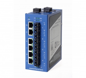
DIN-rail Gigabit Unmanaged Industrial Ethernet Switches
*Up to 4 Gigabit Combo Ports
*Elastic configuration, 100Base fiber port with SC/ST connectors, multi-mode/single-mode models are available
*Multiple power inputs include low voltage redundant power models and 220VAC models
*Broadcasting Storm Controller
Specifications:
* Technology
Network Standards:
IEEE802.3 10Base-T
IEEE802.3u 100BaseT(X) and 100BaseFX
IEEE802.3ad 1000Base(X)
IEEE802.3z 1000BaseSX/LX/HLX/ZX
IEEE802.3x Flow Control
Broadcasting Storm Control:Automatic
Flow Control:Full/Half Duplex Back Pressure Flow Control
* Interface
RJ45 Port Connectors:10/100Base(X) or 10/100/1000BaseT(X) Auto-Negotiation
Fiber Port Connectors:1000BaseSX/CX/LHX/ZX(SFP slots, LC connectors)
LED Indicators:Power, Port Status, 10/100/1000M
* Power Requirements
Low Voltage Range:12~36VDC; 10~24VAC
High Voltage Range:200~350VDC; 165~265VAC
Connection:Standard 4 Pin Dual Power Connector
* Optical Fiber
| Mode | Typical Dist | Wavelength | Cable Size | TX Power | Rx Sensitivity | Transmission speed |
| Multi | 2km | 1310nm | 62.5/125um | -23.5~-14dBm | < -35dBm | 10/100/1000Mbps |
| Single | 15km | 1310nm | 9/125um | -15~-8dBm | < -35dBm | 10/100/1000Mbps |
* Physical Characteristics
Case:Slim Metal Case, IP40 Design
Dimensions:(W×H×D):
HFD10-2G:89×144×125mm
HFD18-2G:70×149×130mm
HFD28-4G:91×166×130mm
DIN Rail or Panel Mounting
* Environment Limits
Standard Temp Models:-10℃ to 60℃
Extended Temp Models:-40℃ to 75℃
Storage Temperature:-40 to 85℃
Ambient Relative Humidity: 10 to 95%(Non-condensing)
* Agency Approvals
EMI:FCC Part15, CISPR(EN55022) Class A
EMS:
EN61000-4-2(ESD), Lv3
EN61000-4-3(RS), Lv3
EN61000-4-4(EFT), Lv3
EN61000-4-5(Surge), Lv3
EN61000-4-6(CS), Lv3
* Warranty
Warranty Period:5 years
* Ordering Information
| Product Model | Connectors | |||||
| Standard Temperature Models(-10℃~60℃) | Extended Temperature Models(-40℃~75℃) | 10/100/ 1000BaseT(X) Or 1000Base SFP |
10/100 BaseT(X) |
100BaseFX | ||
| Multi-mode, SC Connectors | Single-mode, SC Connectors | |||||
| HFD10-2G Series | ||||||
| HFD10-2G | HFD10-2G-W | 2 | 8 | |||
| HFD10-2G-2SC | HFD10-2G-2SC-W | 2 | 6 | 2 | ||
| HFD10-2G-2SSC | HFD10-2G-2SSC-W | 2 | 6 | 2 | ||
| HFD10-2G-4SC | HFD10-2G-4SC-W | 2 | 4 | 4 | ||
| HFD10-2G-4SSC | HFD10-2G-4SSC-W | 2 | 4 | 4 | ||
| HFD18-2G Series | ||||||
| HFD18-2G | HFD18-2G-W | 2 | 16 | |||
| HFD18-2G-2SC | HFD18-2G-2SC-W | 2 | 14 | 2 | ||
| HFD18-2G-2SSC | HFD18-2G-2SSC-W | 2 | 14 | 2 | ||
| HFD18-2G-4SC | HFD18-2G-4SC-W | 2 | 12 | 4 | ||
| HFD18-2G-4SSC | HFD18-2G-4SSC-W | 2 | 12 | 4 | ||
| HFD28-4G Series | ||||||
| HFD28-4G | HFD28-4G-W | 4 | 24 | |||
| HFD28-4G-2SC | HFD28-4G-2SC-W | 4 | 22 | 2 | ||
| HFD28-4G-2SSC | HFD28-4G-2SSC-W | 4 | 22 | 2 | ||
| HFD28-4G-4SC | HFD28-4G-4SC-W | 4 | 20 | 4 | ||
| HFD28-4G-4SSC | HFD28-4G-4SSC-W | 4 | 20 | 4 | ||
| HFD28-4G-6SC | HFD28-4G-6SC-W | 4 | 18 | 6 | ||
| HFD28-4G-6SSC | HFD28-4G-6SSC-W | 4 | 18 | 6 | ||
* All fiber cables can be equipped with ST or SC connectors
* Typical Distance:Multi mode<15km; Single mode: Ranging from 15km to 120km
* The standard models are powered by 24VDC,110-220VAC/DC customized models are also available
Unmanaged Industrial Ethernet Switch 10/100M
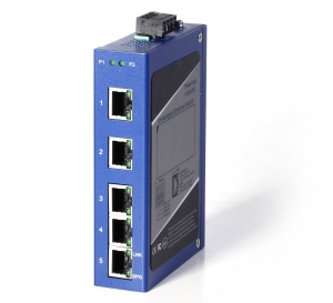
DIN-rail Unmanaged Industrial Ethernet Switch with 10/100M
10/100BaseT(X), 100BaseFX(SC/ST Connectors)
Low Voltage redeundant AC/DC Power Inputs
Metal Case with IP40 Protection
Broadcasting Storm Control
Operating Temperature:-40℃~75℃
Specifications
Technology
- Network Standards:
- IEEE802.3 10Base-T
- IEEE802.3u 100BaseT(X) and 100BaseFX
- IEEE802.3x Flow Control
- Processing Type:Store and Forward
- MAC Address:8K MAC Address Table
- Broadcasting Storm Control:Automatic
- Flow Control:Full/Half Duplex Back Pressure Flow Control
Interface
- RJ45 Port Connectors:10/100Base Auto-sensing, Full/Half Duplex MDI/MDI-X Auto-Negotiation
- Fiber Port Connectors:100BaseFX, SC or ST connectors, Single-Mode or Multi-Mode
- LED Indicators:Power, Port Status
Power Requirements
- Low Voltage Range:12~36VDC; 10~24VAC
- High Voltage Range:200~350VDC; 165~265VAC
- Connection:Standard 4 Pin Dual Power Connector
Optical Fiber
| Mode | Typical Dist | Wavelength | Cable Size | TX Power | Rx Sensitivity | Transmission speed |
| Multi | 2km | 1310nm | 62.5/125um | -23.5~-14dBm | < -35dBm | 10/100Mbps |
| Single | 15km | 1310nm | 9/125um | -15~-8dBm | < -35dBm | 10/100Mbps |
Physical Characteristics
- Case:Slim Metal Case, IP40 Design
- Dimensions:(W×H×D):
- HFD5:30×127×80mm
- HFD8:44×130×95mm
- HFD16:70×149×130mm
- HFD24:91×149×130mm
- DIN Rail or Panel Mounting
Environment Limits
- Standard Temp Models:-10˚C to 60˚C
- Extended Temp Models:-40˚C to 75˚C
- Storage Temperature:-40 to 85℃
- Ambient Relative Humidity: 10 to 95%(Non-condensing)
Agency Approvals
- EMI:FCC Part15, CISPR(EN55022) Class A
- EMS:
EN61000-4-2(ESD), Lv3
EN61000-4-3(RS), Lv3
EN61000-4-4(EFT), Lv3
EN61000-4-5(Surge), Lv3
EN61000-4-6(CS), Lv3
Warranty
Warranty Period:5 years
Ordering Information
| Product Model | Connectors | ||||
| Standard Temperature Models(-10℃~60℃) | Extended Temperature Models(-40℃~75℃) | 10/100BaseT(X) | 100BaseFX | ||
| MM, SC Connectors | SM, SC Connectors | ||||
| HFD5 Series | |||||
| HFD5 | HFD5-W | 5 | |||
| HFD5-SC | HFD5-SC-W | 4 | 1 | ||
| HFD5-SSC | HFD5-SSC-W | 4 | 1 | ||
| HFD5-2SC | HFD5-2SC-W | 3 | 2 | ||
| HFD5-2SSC | HFD5-2SSC-W | 3 | 2 | ||
| HFD8 Series | |||||
| HFD8 | HFD8-W | 8 | |||
| HFD8-2SC | HFD8-2SC-W | 6 | 2 | ||
| HFD8-2SSC | HFD8-2SSC-W | 6 | 2 | ||
| HFD8-4SC | HFD8-4SC-W | 4 | 4 | ||
| HFD8-4SSC | HFD8-4SSC-W | 4 | 4 | ||
| HFD16 Series | |||||
| HFD16 | HFD16-W | 16 | |||
| HFD16-2SC | HFD16-2SC-W | 14 | 2 | ||
| HFD16-2SSC | HFD16-2SSC-W | 14 | 2 | ||
| HFD16-4SC | HFD16-4SC-W | 12 | 4 | ||
| HFD16-4SSC | HFD16-4SSC-W | 12 | 4 | ||
| HFD24 Series | |||||
| HFD24 | HFD24-W | 24 | |||
| HFD24-2SC | HFD24-2SC-W | 22 | 2 | ||
| HFD24-2SSC | HFD24-2SSC-W | 22 | 2 | ||
| HFD24-4SC | HFD24-4SC-W | 20 | 4 | ||
| HFD24-4SSC | HFD24-4SSC-W | 20 | 4 | ||
| HFD24-6SC | HFD24-6SC-W | 18 | 6 | ||
| HFD24-6SSC | HFD24-6SSC-W | 18 | 6 | ||
- All fiber cables can be equipped with ST or SC connectors
- Typical Distance:Multi mode<15km; Single mode: Ranging from 15km to 120km
- The standard models are powered by 24VDC, 110-220VAC/DC customized models are also available
Power Meter Corrector(Zero Voltage Drop)
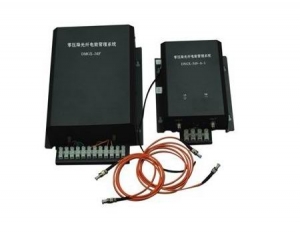
Power Factror Correction System
The power meter factor correction system is designed to correct the power meter’s reading value,which can finally help the utility redeem the economic loss caused by power meter’s deviation or error. The system can help the utility reduce 10% economic loss,which also means it will increase 10% revenue to the utility or other kind of power supply sectors.
Product features
The basic principle of this system : At the secondary terminal of PT, the device collects signal to analog voltage, then carries out a transformation to digital light signal sending to receiver in control room, which is then reduced to an analog voltage signal that is measured by the power meter. In order to improve reliability, the system has a back-up power supply and automatic diagnosis and fault switching function. which guarantees a continuous and reliable measurement of electrical energy.
Signal switching function
In normal condition, voltage signals of electric energy meter is received from the Zero Voltage drop receiver. Once the device is faulty and the output is not normally, the device automatically detects it and switches to PT secondary voltage to continue to measure. This avoids the electric energy’s loss. The device give an acoustic alarm and signal switching light is on at the same time. The receiver can switch automatically so that the digital signal is converted to a voltage signal to the power meter.The electric energy measurement has no losses in the switching process.
Lacking phase alarm fuction
When any fiber (or voltage signal) is disconnected or wrong,The device beeps acoustic alarm and signal switching light is on, the signal is switched to PT secondary voltage signal to continue to measure. The energy measurement has no loss.
Dry contact function
In normal condition, once the dry contact is disconnected. When the device gives an acoustic alarm, dry contact is connected. This can be transmit signal to remote control unit.
Technical Specifications
1.Voltage signal accuracy: rated primary voltage 80%——120%, ahead of 0.05%.
2.Work environment temperature range:
Indoor part A:-5℃—+40℃
outdoor part B:-5℃— +55℃. C:-30℃—+55℃
3.Electromagnetic compatibility: IEC 60044-7 GB/T 20840.7-2007
4. Optical fiber standard: 4 - core
multimode, core diameter: 62.5/125, numerical value aperture≥0.27
Active Power Filter (APF)

Active Power Filter(APF Harmonic Correction)
Description:
BE-APF active power filter (hereinafter referred to as BE-APF), a new solution for harmonic control based on dynamic harmonic elimination technologies, can eliminate the grid harmonic with help of the advanced dynamic real-time tracking and compensation technologies. It can monitor the current waveform produced by the nonlinear load in real time, separate the harmonic component, and inject the harmonic currents of corresponding value and opposite directions to the grid, achieving the harmonic elimination function. All the indexes on technical performance of the BE-APF have reached the equal level of the equivalent products both at home and abroad and both the cost and the technology have achieved revolutionary breakthrough. Thanks to the new process design, the size is dramatically reduced, saving the precious space in the machine room and significantly lowering the threshold for the enterprise user to use the active filter technology.
BE-APF is a power electronic device of large power based on the current detection and current injection techniques. Its working principle is as follows: The waveform of the load current shall be detected in real time to obtain the harmonic current component to be compensated, which then shall be converted in direction, and the IGBT triggering shall be controlled to inject the reversed current to the power supply system, realizing the function of harmonic elimination (offset) and further improving the safety and reliability of the electrical system as well as achieving the goals of energy efficiency.
BE-APF can be viewed as a current source where a harmonic current is provided at the main connection and the harmonic current is opposite in direction to the total harmonic current produced by the nonlinear load. The grid is still running with the fundamental current before the BE-APF is connected to the load.
Since the compensation current of BE-APF is regular, the compensation quality is independent from the network impedance and the power source voltage distortion produced by voltage resonance, dip or flicker. The internal definition of the compensation current is designed to protect the equipment from damaged by over-current, and other loads connected to the power source are free from impact by parallel with the active filter. These features are applied especially to the pulse control system.
Product features:
Real-time monitoring
BE-APF can monitor the energy quality of the distribution system, through which, the followings can be read in real time: THDi and THDu on the grid and/or load sides, the phase current values, and the effect waveform diagram before/after compensation as well as the compensation current values generated by BE-APF and the waveform and other data on energy quality. The operation is simple with easy data reading.
System setting
In the monitoring system of BE-APF, the followings can be set: the working mode, date, CT ratio and the compensation mode etc. where the password shall be entered to ensure the independent and safe running. All the setting options shall be recorded and kept in the system.
Background monitoring
BE-APF is designed with RS485 and the network interfaces so that it can communicate with the computer via data or network lines. The special background monitoring software can be installed in the computer terminal and then the remote operation and control are available for BE-APF, offering huge convenience to its running.
Technical features of BE-APF
All the components are imported quality brands to ensure the quality;
The 3DSP+CPLD totally digital control mode is used to achieve high stability and reliability and eliminate the harmonic accurately;
It can filter dynamically the 2nd~50th harmonic in real time or select optionally the typical characteristic harmonics of various orders present in the grid phase and zero lines;
Many compensation functions such as harmonic compensation, Var compensation and imbalance compensation etc are provided so that the user can select the desired one;
For the APF of three phases and four lines, its capacity to filter the harmonic on the zero line is as three times as that on the phase lines, which is designed for the harmonic over-load on the zero line due to excessive single-phase loads (The 3rd harmonic current on the zero line can reach as three times as that on the phase line due to equal phase position and superimposition) and the imbalanced phases.
The operation is simple thanks to the friendly operation and display man-machine interfaces, and the data and curves can be displayed in real time;
The modular cabinet design is adopted for flexible assembly (Rack and wall-mounted types);
Various effective protection measures are provided to protect the distribution system and the internal equipment from any adverse impact in normal and/or abnormal conditions, including various protection functions (over-load, over/under-voltage, internal faults etc.). It can automatically limit the compensation current in a reasonable manner according to the load variation so that the device will be free from over-current and it can avoid over-compensation while filtering. In addition, the APF high-frequency carrier will not feed back to the grid so that it will not result in any interference on the power supply system and the system equipment.
It is designed with RS485 interface for communication with PC;
It is independent from the impedance of the grid system and thus free from impact of the impedance of the grid system and no resonance and harmonic voltage enlargement will occur. Obviously it is designed with good safety;
It is designed with good extension performance and several APFs can be applied in shunt.
Technical Specifications:
| Harmonic Correction |
| Rated compensation capacity: 25A,35A,50A,60A,75A,100A,Modularized,Free parallel extended capacity |
| Input |
| Work Voltage(V): 380V -40%~+20% |
| Work Frequency: 50/60Hz +/-10% |
| Performance Index |
| Machine Efficiency: >97% |
| Filter Ability: THDi<5% |
| Filter Range: 2~50 times |
| Response Time: <300μs |
| Full Response Time: <10ms |
| Neutral Line Filter Ability: 3 times as Phase Line |
| IGBT Frequency: 20kHz |
| Self-diagnosis and Protection: Yes |
| Communication Interface: RS232, RS485 ,Ethernet |
| Protocol: Modbus |
| Mount: Wall or Rack |
| Protection Grade: IP20 |
| Surge Protection: 20kA |
| Parallel Nodes: 6 pieces |
| CT Transformer: 300/5~4000/5 |
| Environment Condition |
| Work Temperature: 0℃~50℃ |
| Storage Temperature: -20℃~70℃ |
| Humidity: 95%,No condensing |
| Altitude: ≤1500m,1500~4000m,Refer to GB/T3859.2,Every 100m increase,1% Power Reduction |
Application:
Commercial Buildings, UPS, Computer Center, Elevator, Escalator, Cableways, Residential Buildings, Hospitals, TV and Broadcasting Stations, Air Conditioning System, Energy-saving Lights, Subways, Oil and Gas Plants, Electric Railways, New Energy(solar,wind farm), Steel Plant, Cement Plant, Water Treatment, Automobile Factory, Machinery Factory, Ship Yard and so on.
Fast Circuit Breaking Control System
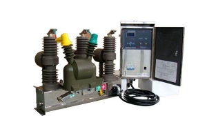
Introduction about BE-IBS1000 Fast breaker control system.
City and rural distribution network of power reliability has been is power sector pursuit of a target, but, due to distribution network structure of complex and load of diversity, plus protection device of some defects, led to has in distribution network in the, once a user appeared fault, is will led to substation 10KV distribution line export protection action, occurred circuit breaker device trip, appeared big area blackout accident, has may caused personal hurt, and equipment damage and products scrap, economic loss. So, how to ensure that when a user fails 10KV power distribution network, sound judgment and correct the fault, without affecting the other users in the feeder circuit of power supply reliability, a key issue is the electricity sector that need to be solved.
In order to ensure the reliability of distribution network power supply, when the user fails, must be cut off as soon as possible points of failure, such as faults in its segment, or fault line is when the user switches inside time frame but its protection and substation protection occurred with no time, user-side breaker or the discrete nature of time, will cause the substation feeder switch protection tripping. If fault nature is permanent of, substation coincide not success, is a in the pressure user territories within of accident will makes whole article distribution line blackout, this in distribution network in the common of spread accident, this on led to has Dang user appeared fault Shi, caused the feed road outlet short-circuit device leapfrog trip, appeared big area blackout of accident, makes power in processing accident and economic compensation, aspects brings great of inconvenience.
Based on IGBT high-voltage side switch controller is the ideal equipment to solve spreading incidents mentioned above, the device is installed on the user's side, when a user fails, prompt removal of the point of failure, and ensure reliable power supply of the feeder circuit to another user.
Prtoduction Feature and Benefits:
The basic function of controller
Protection:
• Reflect phase to phase fault-phase instantaneous trip protection and overcurrent (two parts). Independent setting of switching.
• Second harmonic restraint: the ability to distinguish between current and inrush current, ensure correct operation under fault conditions, current circumstances not to miss the action, especially suitable for multilevel switch and power supply circuit.
• Separate overcurrent acceleration section: mainly for accelerated after the closing.
• Overload protection.
• Reflect low resistance grounding system grounding fault of two-zero-sequence current protection setting for the trip or alarm.
• Low voltage protection
• Reclosing function three times. In addition to this protection can start outside the reclosing, also considered stealing jump starting reclosure of circuit breaker program. Select 0~3 time coincidence function, each overlapping time independent setting.
• Overcurrent inverse-time overcurrent protection.
Remote control functions:
• 3-channel remote signal into the acquisition (of which 2 can be configured as non-power input, 1-channel signal input).
• Switch remote control jump, closing.
• 2 way signal output.
Other features:
• Measuring voltage, current, power meter data, such as information acquisition, save to cloud server through GPRS.
• High speed RS485 PROFIBUS optional standard IEC101, statutes, transfer rate of up to 19.2kbps.
Technical Specifications of the main Controller:
| No | Value | Remark | |
| 1 | Input voltage | 220VAC | The built in voltage transformer converts from first side |
| 2 |
Permitted fluctuation range of input voltage |
±20% | |
| 3 | Power cosumption | <10W | |
| 4 |
Sampling phase current input values |
0.01~100A | Second current’s more than 100A is allowed to saturate |
| 5 |
Sample of zero-sequence current input value |
0.001A~10A |
Zero-sequence second current’s more than 100A is allowed to saturate |
| 6 |
The allowed sampling error value of power input |
±3% |
Saturated zone is not confined |
| 7 |
Inter-phase protection current’s setting value range |
0.01A~100A |
When it’s 0,the corresponding protection function is switched off |
| 8 |
Inter-phase protection action’s latency time value |
Adjustable | 0.01~100 Seconds |
| 9 |
Zero-sequence protection current’s setting value range |
Adjustable |
When it’s 0,the corresponding protection function is switched off |
| 10 |
Zero-sequence protection action’s latency time value |
0~7200s | Adjustable |
| 11 | Reclosing times | 0~3 times, adjustable | When it’s 0,the reclsoure is off |
| 12 | The first reclosing time | Adjustable | 0.3~15 seconds |
| 13 | The 2nd and 3rd reclosing time | Adjustable | 0.3~50 seconds |
| 14 | Setting value error | ±3% | |
| 15 | Insulation resistance | >100MΩ/DC500V |
1.Out terminal connected together to ground 2.Power input terminal to power and switch controller’s output terminals 3.Switc status input terminal to power and switch controller’s output terminal |
| 16 |
power-frequency withstand voltage |
2000V/1min | Same as above |
| 17 | High voltage endurance |
5000V,1.2/50μS + or - three times |
1.Power and controller’s output terminal to ground 2.Power input terminal to ground |
.
Power Theft Monitoring System(Electricity Theft Detection)
Electricity Theft Monitoring System(Power Theft Detection)
Introduction of Electricity Theft Monitoring System
Some enterprises or people,especially the high energy-consumption factories are addicted to stealing electricity to save the electricity cost,which caused the great loss to the electricity distribution companies and disordered the power industry. Because of the new electricity theft technology and the electricity theft devices are becoming more and more intelligent,the anti-theft job is faced with the unprecedented difficulty.
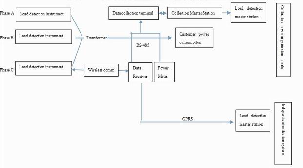
In order to solve these problems and help power distribution companies to detect the electricity-theft actions and crack down on the theft.Our company developed out a new “electricity theft monitoring system”. The system collect the first data by load detection device and compare it with the second data collected by user’s power meter.it can timely monitor the users’ electricity consumption value and avoid the theft.
The electric theft monitoring system is designed for monitoring the industrial and commercial consumption of electricity. The system is the outcome of our efforts for years in the power monitoring system.The system is quite effective and reliable,which is the good friend of power grid distribution enterprises
The Structure of the Anti-theft System(Especially for independent substation users)
The electricity theft monitoring system is applied into anti-theft field and it’s special for the industrial and commercial power consumers.The system consists of Load detection instrument,wireless data receiver and Master station.
The Advantages of the Electric theft monitoring System
1.High reliability,hard to be damaged
2.Timely monitoring
3.High efficiency,solve the theft from the root.
4.Economical, the system’s cost is much lower than the amount of electricity that was stolen.
5.Easy and simple installation, can be installed even when there is electricity.
BE Provides Industrial Control and Automation Systems Solutions

As a leading industrial automation products manufacturer, we offer efficient and reliable products and solutions to serve global customers. With the integration of drives, controllers, motion, sensors, communication devices and software.
Our Field:
we cooperate with factories such as textiles factory, beverage factory, printing and packaging factory, chemical,steel plant,paper mill and so on. We also provide energy-saving solutions, drive systems, facility management control systems, visualization and surveillance solutions, robot stations, power quality solutions and factory automation for the electronics and high tech, oil and gas, chemicals, metallurgy, transportation,building automation(BAS) and municipal construction sectors.
Our Advantage:
We manufacture products, so our total cost is lower than competitors.
We have a young and talented team who is efficient and enthusiastic.
BE Substation Automation SCADA System
BE(Bueno Electric) provides development services to increase substation automation network reliability
SCADA development
With its many years of experience in developing world-class SCADA components and deploying them at our customers’ facilities, BE is capable of redesigning and modernizing SCADA systems to introduce new functionality without time-to-market losses for any vendor on the market.
Intellectual Electronic Devices Development
BE’s Energy Practice builds today’s smart substations, recommends the right technology, deploys and develops substation automation system software, tests IEDs, manages security issues, and testis, tunes, and secures wireless networks.
Different Devices Integration
Different devices use different protocols(Such as Modbus,IEC61850,IEC-60870-51-1/102/103/104,DNP3,OPC) and communication standards, but the BE team can integrate those into a seamless network of interconnected managed and monitored devices that increase substation reliability and performance.
Data Management & Acquisition
With substation automation, the number of data sources is continually growing causing a parallel increase in the data that must be processed to improve substation reliability and network utilization. BE helps to manage high volumes of data online and develops complex visualization solutions and frameworks.
End-to-end solution delivery
Full-cycle application development and support
Architecture design and analysis
Adaptors and connectors to legacy systems and metering systems development
Reporting, analysis, and visualization tools integration
In-depth knowledge of interoperability standards
Full-cycle hardware design, development, and maintenance
Quality assurance and development processes