
Super User
What code the GPS outputs?
The GPS outputs NMEA0183 Code
The whole earth is divided into two fourteenth time zones, with each time zone having its own local time. In international radio communications, for the sake of uniformity, use a unified Time, called Universal Time Coordinated. The UTC, like Greenwich Mean Time on average, is the same as in London, England.
GPS is NMEA0183 code output, the GPGGA and GPRMC are clearly defined, such as: $GPGGA, 100639.00, 3109.79801, N, 12123.38493 E, 1,07,1.20, 21.9 M, 8.0 M, and 100639.00 * 5 d said the UTC time at 10 6 minutes and 39 seconds, if you count into Beijing time, add 8 hours, 18 points is 6 minutes and 39 seconds. A, $GPRMC, 100640.00, 3109.79805, N, 12123.38495 E, 0.008, 091106,,, A * 7 c 091106 said on November 9, 6 years, is also A UTC time, if the date is Beijing time, want to consider together with time.
The time of the GPS system is different from UTC time, which is a leap second, because the UTC time is adjustable, and the GPS time is continuous, the leap second is reflected in the navigation message in the next line. Beijing time = GPS time + 8 hours - leap seconds. GPGGA, GPRMC in itself has been convert GPS time to UTC time, so the time to Beijing just 8 hours, the GPS time is shown as on February 28, 0 (if not a leap year this year), Beijing is 28 February 8; The GPS time will be 15 on February 27 and Beijing time will be 23 hours on February 27. When GPS time is 18 February, Beijing time is February 28. The GPS time is 18 on February 28, while Beijing time is March 1, 2.
At present the NTP (Network Time Protocol) Network equipment Network Time server is to provide accurate, standard, safe, reliable and versatile Time service the best solution, can provide precise synchronization clock signal, support the standard NTP and SNTP (Simple NTP) Network protocols for fashion, using safety MD5 encryption protocols and certificate, complete with logging and USB port to download function, can support Network pair (NTP), a serial port, 10 MHZ frequency signal, the output 1 PPS pulse signal, the dry contacts alarm signal, and other functions.
The 4-20mA Current Loop
The 4-2OmA current loop has been with us for so long that it's become rather taken for granted in the industrial and process sectors alike. Its popularity comes from its ease of use and its performance. However, just because something is that ubiquitous doesn't mean we're all necessarily getting the best out of our current loops.
A big benefit of the current loop is its simple wiring just the two wires. The supply voltage and measuring current are supplied over the same two wires. Zero offset of the base current (ie. 4mA) makes cable break detection simple: if the current suddenly drops to zero, you have a cable break. In addition, the current signal is immune to any stray electrical
interference, and a current signal can be transmitted over long distances.
Typical wiring for current output transducer.
You can think of the current loop itself as being analogous to a water system. You have a hose pipe (the wires) and a source tap (the power supply). You have a spray gun that regulates the flow (the transducer). You can have other equipment on the line, but it all has to be connected
together in a ring Ioop. The more holes (devices) you have on the hose pipe, the higher the pressure will be required from the tap. Relating all that back to the current loop, you see a power supply, a transducer and one or more pieces of instrumentation all connected together in a ring.
You'll often hear things referred to as being either active or passive. Some instruments have an active output which includes both the control of the current in the loop as well as provide the supply voltage. This is typically specified as being a 4-20mA output into 10-750 Ohms, or something similar. A passive input would be a simple resistor input that
has a voltage drop to be factored into the equation once the supply voltage is chosen. This is typically specified as a 4-20mA input into 10 Ohm.
Working out the power supply requirement is a simple matter of adding up all the units in the loop at maximum current of 20mA. As an example, suppose you have a sensor 'regulator' which requires minimum 12V DC and instrumentation of 10 Ohm input:
10 Ohm x 20mA = 0.2V
So, for this circuit, a 12.2V minimum supply is required, the sensor's maximum voltage might be specified at 30V, so a 24V supply would be all the circuit requirements with spare capacity to boot.
In order to measure the current loop it is necessary to break the loop and insert a current meter into it. You can also measure the voltage across the various components by in the loop, such as the voltage out of the power supply, the voltage over a sensor, and the voltages over the various pieces of instrumentation. This information will give you a
good picture of what is happening within the loop.
Multi-instrument 4-20mA current loop with panel meter, chart recorder, computers, etc.
A question which is sometimes asked is whether it is possible to use single power supply over several loops. This is possible, but you have to ensure that the power supply can give enough current to meet the needs of multiple loops. It is also the case that the current loops will have the same zero negative reference, which can cause a ground loop. In addition, interference from one loop can affect all the other loops driven from the one supply.
About NTP Version 4
NTP has been under development for almost 30 years, but the paint ain't dry even now. This release of the NTP Version 4 (NTPv4) distribution for Unix, VMS and Windows incorporates new features and refinements, but retaining backwards compatibility with older versions, including NTPv3 and NTPv2, but not NTPv1. Support for NTPv1 has been discontinued because of certain security vulnerabilities.
New Features
The behavior of the daemon at startup has been considerably improved. The time to measure the frequency and correct an initial offset error when started for the first time is now no more than ten minutes. Upon restart, it takes no more than five minutes to reduce the initial offset to less than one millisecond without adversely affecting the frequency. This avoids a subsequent frequency correction which could take up to several hours.
A new feature called interleaved mode can be used in NTP symmetric and broadcast modes. It is designed to improve accuracy by minimizing errors due to queuing and transmission delays. It is described on the NTP Interleaved Modes page.
The huff-n'-puff filter is designed to avoid large errors with DSL circuits and highly asymmetrical traffic, as when downloading large files. Details are on the The Huff-n'-Puff Filter page.
A new feature called orphan mode provides an automatic, subnet-wide synchronization feature with multiple sources. It provides reliable backup in isolated networks or in pr when Internet sources have become unavailable. See the Orphan Mode page for further information.
This release includes comprehensive packet rate management tools to help reduce the level of spurious network traffic and protect the busiest servers from overload. There is support for the optional Kiss-o'-Death (KoD) packet intended to slow down an abusive client. See the Rate Management and the Kiss-o'-Death Packet page for further information.
There are two new burst mode features available where special conditions apply. One of these is enabled by the iburst keyword in the server configuration command. It is intended for cases where it is important to set the clock quickly when an association is first mobilized. The other is enabled by the burst keyword in the server configuration command. It is intended for cases where the network attachment requires an initial calling or training procedure. See the Association Management page for further information.
The OpenSSL cryptographic library has replaced the library formerly available from RSA Laboratories. All cryptographic routines except a version of the MD5 message digest algorithm have been removed from the base distribution. All 128-bit and 160-bit message digests algorithms are now supported for both symmetric key and public key cryptosystems. See the Authentication Support page for further information and the Authentication Options page for a list of supported digest algorithms.
This release includes support for Autokey public-key cryptography for authenticating public servers to clients, as described in RFC 5906. This support requires the --enable-autokey option when building the distribution, which is the default is OpenSSL is available. The deployment of Autokey subnets is now considerably simpler than in earlier versions. A subnet naming scheme is now available to filter manycast and pool configurations. Additional information about Autokey is on the Autokey Public Key Authentication page and links from there.
The NTP descrete even simulator has been substantially upgraded, now including scenarios with multiple servers and time-sensitive scripts. This allows the NTP algorithms to be tested in an embedded environment with systematic and pseudo-random network delay and oscillator wander distributions. This has been used to verify correct operation under conditions of extreme error and misconfiguration. See the ntpdsim - Network Time Protocol (NTP) simulator page. A technical description and performance analysis is given in the white papers at the NTP Project Page.
NTPv4 includes three new server discovery schemes, which in most applications can avoid per-host configuration altogether. Two of these are based on IP multicast technology, while the remaining one is based on crafted DNS lookups. See the Automatic NTP Configuration Schemes page for further information.
The status display and event report monitoring functions have been considerably expanded, including new statistics files and event reporting to files and the system log. See the Event Messages and Status Words page for further information.
Several new options have been added for the ntpd command line. For the inveterate knob twiddlers several of the more important performance variables can be changed to fit actual or perceived special conditions. In particular, the tinker and tos commands can be used to adjust thresholds, throw switches and change limits.
The ntpd daemon can be operated in a one-time mode similar to ntpdate, which program is headed for retirement. See the ntpd - Network Time Protocol (NTP) daemon page for the new features.
Why Choose BE GPS Clocks?
When someone refers to GPS clock systems, they are talking about the new super-accurate radio transmitter operated clock systems. In order to work properly, It uses a synchronized by a radio-transmitted time code. The systems utilize satellite technology from the various satellites that are scattered in space around the earth, to record time with 100% accuracy.

When a GPS satellite passes overhead, it sends time signals to the GPS receiver. The receiver then sends signals to a radio transmitter and it is rebroadcast to each clock that is programmed to be a part of the system. Each of the clocks is synchronized down to the second.
The letters, "GPS," stand for "Global Positioning System." This was originally a military concept that cost the US Department of Defense $12 billion to design, build and implement. While it was originally intended for military use only, it is no longer exclusive. They are used to help synchronize computer systems. They are considered to be the most accurate timing references, so are used for computerized timing applications and accurate timing references.
Places of business that rely on synchronized time benefit a great deal by implementing GPS clock systems. For example colleges and universities or banking institutions that rely on accurate security logs, are at a distinct advantage when they use it, College administrators appreciate the fact that when a college campus is synchronized, there are fewer class disruptions because of students who arrive to class late. Hospitals that need precise, accurate timing for procedures and testing benefit from them. Companies that use GPS clock systems can also save money by monitoring employees shift changes and breaks and eliminating those extraneous breaks that do not represent the company's best interests.
GPS clock systems do not involve the use of complicated equipment in order to work. They are easy to install and can be installed in a number of different locations in the school, hospital or other business that uses them. Should the electricity ever go out due to inclement weather, the system will continue to perform accurately. This is due to the technology that stores data in a non-volatile memory from the instant the power goes out. When it comes back on, the transmitter will receive the time from the GPS receiver. It then corrects any of the internal data and will send the updated time to system clocks. Any type of power outage that is not extended beyond a reasonable length will not have a significant impact on the accuracy of the GPS clock systems.
The same non-volatile memory also works to automatically change time for Daylight Savings Time. On the day that the time changes, the radio transmitter signals the satellite clock which, in turn, adjusts the clock for Daylight Savings Time. If Daylight Savings Time is not observed in the area where the GPS clock systems are installed, this feature can be disabled.
Facotors that might Interfere with GPS Signal and how to Work with Weak Signal GPS
GPS device relies on the radio signals sent by the GNSS network situated in earth's orbit. The GNSS regularly send signals to aid millions of GPS users. The accuracy of GPS depends on the GPS signal strength that may degrade due to several reasons. The article discusses weak signal GPS.
Current GPS – Optimal Satellite Positioning and Structure
Current GPS System
Millions of GPS users across the world are dependent on the signals sent by the GNSS network in the sky to achieve certain tasks that include determining their location, navigation, tracking something or someone, and mapping areas, among the many other applications of GPS. At the moment, GPS is divided into two categories: civilian and military. Accordingly, the GNSS send signals at L frequencies: L1 for civilians and L2 for sole military purpose.
L2 is highly encrypted and stronger to increase the accuracy of GPS for military. This provision has been made so that no terrorist organization can use the advanced signals on L2 frequency for destruction. Besides, the US reserves the right to alter or limit the signal strengths or angles for both frequencies if required. This is possible because NAVSTAR, the US owned GNSS is the only space based network that is fully functional.
The current GPS constellation is supported by 31 active satellites revolving around the earth in six different orbits, with a minimum of four satellites in each orbit. The GPS system makes sure that the earth based GPS devices and GPS servers receive signals from five or more satellites round the clock (even though a GPS device can function with signals from four satellites).
To enhance the accuracy of GPS device, the orbits are inclined at 55 degrees each, thereby facilitating different, yet direct (straight) paths for the signals to reach earth-based GPS devices without any hindrances. Still, there are several factors that interfere with the GPS signals to create a GPS blackout or to reduce the accuracy of GPS device. The next section checks out what interferes with a GPS signal.
Weak Signal GPS – What Interferes with a GPS Signal
The most common factor that interferes with a GPS signal is what is termed "Urban Canyon." The term refers to the high rise concrete buildings and skyscrapers that do not allow the signals to pass through them. These urban structures either totally
CAN to Multi-drop BUS Fiber Optic Converter
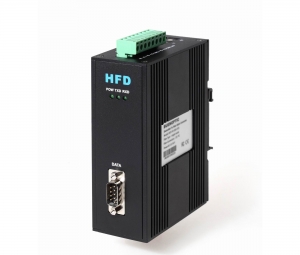
Multi-drop CAN BUS Fiber Media Converter
Product Descriptions:
The HFD series CAN to Fiber Optic Converter support all the transmission speeds (transmission rates):0-1Mbps.The CAN BUS rate is configurable by software,it adopts the new technology,the unique feature of it is it can support complex and long networks,even when it's at 1MB(6500 frames),it can transmit 20km distance.The transmission rate is set automatically as soon as the HFD-FO-CAN MuIlti-drop Bus Fiber Converter receives a frame. The setting or adjustment is dependent on the transmission rate. Depending on the HFD-FO-CAN Settings in automatical mode,Segment monitoring at the optical line.Each receiver monitors the optical line port connected to it for receve frames and status. If faulty frames are received by the receiver, or no single for longer than the maximum permitted time, forwarding of the received signals is blocked until the port status is ok,frames can be received again correctly.
Feature and benefit:
Long distance transmision
High frames: 6500 frames/second
Anti-stream: 1000 frames buffering
Can be used in complex and harsh networks
High Baud rate: 1Mbps(20km distance)
Optional Function: Butter clerance in nominated time
Network Topology: Multi-drop Bus
|
Technical Data |
|
|
Voltage/power supply |
5V/12V/24V DC,Dual Power Supply |
|
Operating voltage |
9 V to 30 V DC, typ. 24 V, |
|
Current consumption |
typ. 80 mA@24V> |
|
Output voltage/current (Pin 6 Sub-D socket) |
5 V +5%,–10%/ 90 mA |
|
Signaling contact Signal transmission |
Max .switch DC24V@2A or This email address is being protected from spambots. You need JavaScript enabled to view it. |
|
Transmission rate |
0-1Mbps |
|
Setting transmission rate |
Automatic or Switch setting |
|
Bit error rate |
< 10-9 |
|
Electrical port |
Terminal or DB9 |
|
Input/output signal |
CAN2.0A, CAN2.0B,ISO-11898 |
|
PIN assignment |
|
|
Optical ports |
2 or 4 (4 as standard) |
|
Wavelength |
SM:1310nm, MM:850 nm |
|
optical power:– in glass fiber 9/125um – in glass fiber G 62.5/125 |
-9dBm – -18 dBm -13 dBm – -20 dBm |
|
Receiver sensitivity |
-34dBm |
|
Transmission distance:with glass fiber 9/125um with glass fiber G 62,5/125 |
0 – 20,000 m (0.3 dB/km) 0 – 3,000 m (2.0 dB/km) |
|
Connector |
ST/FC/SC |
|
Others |
|
|
Ambient temperature |
-30 °C to +70 °C |
|
Storage temperature |
–40 °C to +85 °C |
|
Relative humidity |
<95 %, non-condensing |
|
Protection class |
IP 30 |
|
Dimensions (W x H x D) |
43(W) x 88.5(D) x 124.5(H) mm |
|
Housing material/Color |
Die-cast zinc/Black |
|
Weight |
approx. 650 g |
Electromagnetic compatibility (EMC)
Limit class B (EN 55022)
EN 61000-4-2
EN 61000-4-3)
Burst: On power supply lines and shielded RS 485 bus lines: ±2 kV (EN 61000-4-4)
Surge: Power lines: ±1 kV symmetrical,Shielded RS 485 lines: ±2 kV asymmetrical (EN 61000-4-5)
Application: The HFD-FO-CAN multi drop bus Fiber converter can be used in fire alarm system,radar system,security,industrial automation,solar plant and other industrial fields.
Ordering Information:
|
Model Number |
Description |
Fiber No. |
Fiber Mode |
Fiber Connector |
|
HFD-FO-CAN-M2M |
Multi Drop Bus Link,Dual Fiber(BI-DI), 2km |
2 |
Multi Mode |
ST/SC/FC |
|
HFD-FO-CAN-M4M |
Multi Drop Bus Link,4 Fiber, 2km |
4 |
Multi Mode |
ST/SC/FC |
|
HFD-FO-CAN-M2S |
Multi Drop Bus Link,Dual Fiber(BI-DI), 20km |
2 |
Single Mode |
ST/SC/FC |
|
HFD-FO-CAN-M4S |
Multi Drop Bus Link,4 Fiber, 20km |
4 |
Single Mode |
ST/SC/FC |
The Importance of Monitoring of Smart Meters
The Importance of Monitoring of Smart Meters
In the more than 100 years history of the electric power industry, "smart meters" is still in the early stages of deployment and use. Because of the electric meter is the front end of the electric power company "register", must be very accurate.
Although there are a large number of requirements for the meters, performance specifications and regulations, and electric power company is trying to ensure the accuracy of meter, but in fact, once certified meter design, manufacture and installation, most of the electric meter accuracy confirmation just only stay in production at the end of the factory test phase. Specific meters in front of the retired live performance can only be estimated by statistical sample test.
In addition, the power is the primary sources of revenue loss power co., LTD. Although usually think the problem is mainly developing economies, but in many developed regions is increasingly serious. Britain, for example, natural gas and electricity markets (Ofgem) office in July 2013, issued a report titled "stop power - diagnosis", which estimates the power theft happened year after year more than 200 million pounds, power companies need to invest another 25 million pounds preventing electricity-stolen, repair or replace equipment been tampered with.
1.The power meter's accuracy is critical
Smart meters relative to electronic and mechanical connectivity is the main advantage of the electric meter. Networking smart meters can remote report of electricity, power management, collecting data and using time to prevent certain types of power. The measuring of electric meter itself is the key, however, is it possible to function to perform more sophisticated diagnosis?
Other industries have the function of the key tasks, such as automotive and industrial, the diagnosis, introducing the concept of "functions", its essence is to check equipment to determine whether the used before use, and then the normal operation. One of such functions of electric power meter industry is the scene during the service life of electric meter accuracy.
Current meter sample test execution site, only rely on site meter internal components remain within the scope of the calibration to estimate accuracy, but this method exists risk. On-site monitoring accuracy is important, because precision affected by the sensor, the sensor is exposed to high current, voltage events and harsh environment. Therefore, diagnosis must include monitoring the electric meter, including sensors and all electronic components.
Electric meter accuracy check usually requires human intervention, disconnect the scene and using special equipment, so need to spend a lot of cost or the implementation of complex apart to complete the on the spot. However, for each meter of noninvasive monitoring technology can change the dilemma.

2. Opportunity for data analysis
Information system architects need to consider the question: "if can get the accuracy of the deployment of each meter on a regular basis, what do you do?" The ability to eliminate failures and defective goods, but better is to collect and analyze the information of electric meter group.
The monitoring accuracy will not violate any laws and regulations, but it can provide management the advantage of the meter. Per hour or a day to collect information, the data quantity is not too big, but the potential is unlimited.
Figure 1 shows the accuracy of high resolution monitor group, which can extract group differences during service life. So can understand manufacturing batch, supplier, deployment, regional differences or different grid topology.
This data can also be combined with other measures, such as season, temperature, humidity, and power consumption, is used to determine whether the need to improve the future electric meter specifications, to provide more repeatable field measurement.
In addition, knowledge of the performance of the whole group, a goal can be set for the sample test, meet the requirements of regulatory agencies. Implementation of the large data analysis of the electric meter group can make the responsibility of the power companies to better deal with risk.
Three solutions
So far, did not exist, including the meters, on-site operation and self-check accuracy test. It wouldn't change, therefore, to identify and report equipment precision mechanism. The blank highlighted the demand of the new monitoring technology, namely the continuous monitoring site meter accuracy, provide built-in, since the test function, used to check the performance of the electric meter during the whole life. The technology must be in meters run-time monitoring meter accuracy, shall not affect the measurement function at the same time.
To cope with the challenges, ADI company developed mSure technology (as shown in figure 2 green box), aims to inject known reference signal sensor continuous monitor the response of the electric meter. After stacking, sensors can detect at the same time reference signal and load signal. The combined signal from the same path, so existing combination signals at the end of the electronic device digital form.
Detection circuit is the only reference signal from the load signal extraction, once completed this step, the system will have from the sensor to the meter digital representation of transfer function.
The same transfer function can be applied to the load signal to digital, said the change in order to determine the accuracy of power companies. To keep energy data, monitoring signals digitally removed from the signal path, only energy into the measurement data transmission system.
Because has the ability of monitoring sensors and electronic devices, this technology can also be used to detect many existing "tamper-proof" meter cannot identify power method. Even if power company stopped only a few tamper with the event, can significantly improve profitability.
4.Summary
Current meters certified before supply and installation, calibration and factory testing, to ensure a complete set of precision and performance standards, and meet the different level of different areas. Later, electric meter can maintain accuracy can only rely on trust (components quality and statistical test).
By adopting strict meter monitoring method, power companies can use internal connectivity smart meters provide a test precision of the non-invasive, application of big data analysis in order to better understand the precision of electric meter deployment, reduce the power meter.
Analog I O module in the Application of the PLC Signal Processing
In industrial control, some input (such as pressure, temperature, flow rate, rotational speed, etc.) is a continuous change of analog, some actuators (e.g., servo motor, regulating valve, recorder, etc.) for PLC output analog signal, and the PLC CPU can only deal with digital quantity. Analog was first sensor and transmitter is converted into A standard current or voltage, such as 4 ~ 20 ma, 1 ~ 5 v, 0 ~ 10 v, PLC with A/D converter convert them to digital quantity. The digital quantity can be binary, may also be A decimal, plus or minus current or voltage after A/D conversion generally use two's complement representation.
D/A converter converts PLC digital output to analog voltage or current, then to control the actuator. Analog I/O module's main task is to complete A/D conversion (analog input) and D/A conversion (analog output).
(Ⅰ) PLC analog input module
Analog input module, also known as A/D module, the field generated by the sensors and the continuous analog signal is converted into the PLC CPU can receive digital quantity, for 12 bit binary number more commonly, digital quantity the more digits module, the higher resolution.
(Ⅱ) PLC analog output module
Analog output module is also known as D/A module, the PLC CPU to the analog output module convert the digital quantity of external equipment can receive analog (voltage or current). Analog output module receives the digital signal of 12 bit binary number more commonly, digital quantity the more digits module, the higher resolution.
B E's Remote IO Modules Works as the Data Acquisition Module in Substation SCADA
Power substation monitoring and control system can provide real-time information, especially the switch and protection behavior of information (accident alarm information), and make the personnel on duty and system dispatch personnel to grasp the initiative of security control, accident treatment, at the same time can improve the management level of power network, reducing the loss of substation, power distribution, improve the quality of power supply.
A specific monitoring, system objects:
Main microcomputer monitoring system of transformer substation monitoring object has the following several aspects: analog acquisition has a high pressure chamber and main control indoor temperature, humidity and entrance guard. Side of 0.4 kV transformer, 0.4 kV bus voltage, current, active power and reactive power, 0.4 kV each branch line current, temperature of transformer. Standby diesel engine generator voltage, current, active power, reactive power, oil pressure, oil temperature, water temperature, battery voltage, etc. A light on-off switch, circuit breaker switch, the outlet and inlet line of high voltage switch, the main transformer tap switch, main transformer low voltage main switch, the section switch, 0.4 kV each branch line switch, diesel generator circuit switch, etc.
Second, the collection of wisdom of the solution:
Hardware implementation
1. The substation the indoor temperature, humidity and entrance guard
Substation withdraw after one thousand substation fire, often because of not found in time and delay the processing of the accident, cause an accident. In addition, when the thieves broke into substation, lack of effective defense. Therefore, in the high pressure chamber and master control room where installed a number of temperature, humidity sensors, and at the gate of the high pressure chamber and master control room to install active infrared intrusion detectors. When the probe sensor to high temperatures or was broken into, can send the alarm information to the background, moving and switch camera images at the same time, and record the current state of the field.
With RS - 6042 - m to collect temperature and humidity sensor signal. Collect 5 sensor signals.
Using the RS - 6011 - m voltage signal acquisition active infrared intrusion detectors, 16 alarm signals can be collected.
2. The transformer
Side of 0.4 kV transformer, 0.4 kV bus voltage, current, active power and reactive power, 0.4 kV each branch line current, monitoring of transformer operation, can make a timely response when the abnormal situation. Choose transformer itself should take control of the protection device, has the perfect temperature testing and fan control function, using the transformer itself provides platinum resistance, transformer coil temperature, if the temperature of the test more than set threshold, the fan has yet to start, the mandatory start fan. Data in the controller by RS485 interface, can also be transmitted to the monitoring center, execution of transformer condition monitoring.
Using the RS - 6021M for collection side of the transformer, bus voltage, piecewise current, active power and reactive power.
Using the RS - 6042M for collection coil temperature.
Using the RS - 6014M for startup and shutdown fan.
3. The motor and the standby diesel engine generator protection:
With the motor current, voltage, temperature measurement as the foundation, provide comprehensive protection for the motor. With short circuit, start timeout, locked-rotor, unbalanced rotor, ground fault over voltage, temperature, load loss, and under-voltage protection, etc. Through the inspection before the start of busbar voltage, trip circuit is normal, the reliability of the system was further improved.
Standby diesel engine generator voltage, current, active power, reactive power, oil pressure, oil temperature, water temperature, battery voltage, etc. Monitoring of transformer operation, can make a timely response when the abnormal situation.
Using RS - 6021M for acquisition of current, voltage of the motor and diesel engine generator voltage, current, active power, reactive power.
Using the RS - 6042M for motor temperature signal.
With RS - 6041M for acquisition hydraulic diesel engine generator, the oil temperature, water temperature.
4. The switch quantity monitoring
(1) to make industrial TV monitoring system can still work in the evening, the lights of the substation should have the function of the time switch or remote control.
(2) a circuit breaker: on or off or failure in operation of the circuit.
(3) the main transformer tap switch, main transformer low voltage side switches, section switch, 0.4 kV line switch, various loops diesel generator circuit switch, RS - 485 serial communication mode. Can through the communication to realize remote control points/closing, remote measurement value, the remote reading on-off state.
Using RS - 6013M to monitor and control switch.
System schematic diagram
Set of wisdom, power monitoring and control system, the I/O data acquisition module
The data communication function
Substation internal circuit monitor the communication between the host and USES RS 485 Modbus RTU protocol, the communication distance can reach 1, 200 m, baud rate can be set to 1200, 2400, 4800, 2400, 4800, 38400, 57600, 38400.
Third, the conclusion
General distributed substation monitoring and control system equipment, maintenance, installation is simple, high reliability, the function is complete, the user easy to use. Via multiple substation and distribution of factories and mines, this paper described in the monitoring system has received the good effect. Do the power monitoring management gradually to automation, integrated, centralized and intelligent direction
B E Plays the Role Time Synchronization Provider for Swiss Safety Company
After the joint efforts by both companies,B E successfully helped the Swiss Safety engineering company found the safety communication network which is based on IRIG-B and NTP. With the support of B E, the old time synchronized products are remained without the cost and labor waste and the new network is much more flexible and extendable than the old devices.
