
Super User
Ultrasonic Cell Crusher | Homogenizer for Cell Disruption
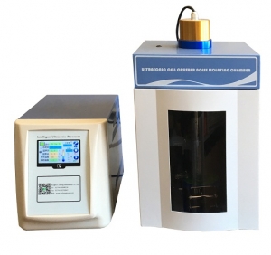
Ultrasonic Cell Crusher | Homogenizer for Cell Disruption (Touch Screen Version)
Product Description
The Ultrasonic Cell disruptor/Crusher(Touch Screen Control) which used 4.3 TFT touch control and upgraded the password protection system, is a multifunctional and multipurpose instrument for ultrasonic processing by cavitation in liquid material. It can be used for a variety of plants and animals, bacteria, viruses, cells and the organization of broken, at the same time can be used to emulsify, separation, scattered, cracking, homogenization, extraction, defoaming, cleaning, nanometer material preparation, graphene dispersion and chemical reactions, etc.
Product Features
1. Large TFT screen Display, Touch control for new version
2. Login Password Protection System for data security
3. 20 groups of experimental data can be set and stored, safe and convenient.
4. The ultrasonic power can be adjusted continuously, and the best experimental conditions can be explored.
5. The program has over-temperature/delay/fault protection settings and alarm system,which can protect the test samples to the maximum extent.
6. High and Low temperature bath is optional which can control the temperature between -40 to 200℃
7. RS232 Interface is optional, which can support the data transmission between the PC and PLC to realize the remote control.
8. We provide the Sound-proof Chamber for standard configuration with perfect transportation.
Application
The instrument is widely used in the fields of biology, microbiology, physics, zoology, agronomy, pharmacy, petroleum, etc. It also can be used in Nanotechnology research such as the dispersion of nanomaterials (nanotubes, graphene, silica, etc.); sample homogenization and emulsification; accelerate dissolution, accelerate chemical reaction and other sample processing.
Technical Specification
|
Model |
BEM-150A |
BEM-650A |
BEM -900A |
BEM -1000A |
BEM -1500A |
BEM -1800A |
BEM -3000A |
|
Frequency |
20-25 |
20-25 |
20-25 |
20-25 |
19-21 |
19.5-20.5 |
19.5-20.5 |
|
(KHz) |
|||||||
|
Power(W) |
0-150 |
0-650 |
0-900W |
10-1000 |
1500 |
20-1800 |
300-3000 |
|
Crushing Capacity |
0.1-150 |
0.1-500 |
0.1-600 |
0.1-700 |
20-1200 |
10-1500 |
100-5000 |
|
(ml) |
|||||||
|
Input &Display(4.3in TFT) |
Touch Control |
Touch Control |
Touch Control |
Touch Control |
Touch Control |
Touch Control |
Touch Control |
|
Login Password |
Yes |
Yes |
Yes |
Yes |
Yes |
Yes |
Yes |
|
Probe(mm) |
Φ6 |
Φ6 |
Φ6 |
Φ6 or 10 |
Φ22 |
Φ20 or 22 |
Φ35 or 50 |
|
Optional Probe(mm) |
Φ2、3、8 |
Φ2、3、8、10、12 |
Φ2、3、8、10、12 |
Φ2、3、8、10、12、15 |
Φ10、15、20、25 |
Φ10、15、20、25 |
Φ15、20、25、35、40、50 |
|
Sample Temperature Protection(℃) |
0-100 |
0-100 |
0-100 |
0-100 |
0-100 |
0-100 |
0-100 |
|
Security System |
Self-diagnosis function, automatic error correction, overload, overtemperature protection ,etc. |
||||||
Probe Option
|
Probe Model |
Inch |
Frequency |
Power Range |
Crushing Capacity |
|
Φ2 |
1/12″ |
20-25KHz |
min-150W |
0.2-5ml |
|
Φ3 |
1/8″ |
20-25KHz |
min-250W |
3-10ml |
|
Φ6 |
1/4″ |
20-25KHz |
20-400W |
10-100ml |
|
Φ10 |
5/12″ |
20-25KHz |
100-600W |
30-300ml |
|
Φ12 |
1/2″ |
20-25KHz |
200-900W |
50-500ml |
|
Φ15 |
5/8″ |
20-25KHz |
300-1000W |
100-600ml |
|
Φ20 |
4/5″ |
19.5-20.5KHz |
400-1100W |
100-1000ml |
|
Φ22 |
5/6″ |
19.5-20.5KHz |
400-1100W |
200-1000ml |
|
Φ25 |
1″ |
19.5-20.5KHz |
800-1500W |
500-1200ml |
Advantages
Advantages of Ultrasonic Homogenizing is very efficient for the reduction of soft and hard particles. The homogenization is based on cavitation. Our Ultrasonic Cell disruptor/Crusher (Touch Screen Control) which used 4.3 TFT touch screen and upgraded the password protection system, is a multifunctional and multipurpose instrument for ultrasonic processing by cavitation in liquid material.
Another advantage is the exact control over the operational parameters influencing the cavitation. The ultrasonic power of our instrument can be adjusted continuously, and the best experimental conditions can be explored.We also have a program that has over-temperature/delay/fault protection settings and alarm system, which can protect the test samples to the maximum extent. We provide the Sound-proof Chamber for standard configuration with perfect transportation.
Ultrasonic Crusher | Disruptor | Disintegrator ( Touch Screen Control)
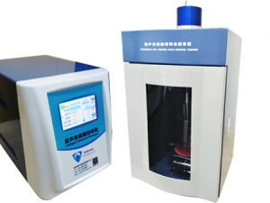
Ultrasonic Crusher | Disrupter | Disintegrator | Probe Sonicator | Ultrasonic Processor
Product Description
The Ultrasonic Disruptor/Crusher(Touch Screen Control) which used 4.3 TFT touch control and upgraded the password protection system, is a multifunctional and multipurpose instrument for ultrasonic processing by cavitation in liquid material. It can be used for a variety of plants and animals, bacteria, viruses, cells and the organization of broken, at the same time can be used to emulsify, separation, scattered, cracking, homogenization, extraction, defoaming, cleaning, nanometer material preparation, graphene dispersion and chemical reactions, etc.
Product Features
1. Large TFT screen Display, Touch control for new version.
2. Login Password Protection System for data security.
3. 20 groups of experimental data can be set and stored, safe and convenient.
4. The ultrasonic power can be adjusted continuously, and the best experimental conditions can be explored.
5. The program has over-temperature/delay/fault protection settings and alarm system,which can protect the test samples to the maximum extent.
6. High and Low temperature bath is optional which can control the temperature between -40 to 200℃
7. RS232 Interface is optional, which can support the data transmission between the PC and PLC to realize the remote control.
8. We provide the Sound-proof Chamber for standard configuration with perfect transportation.
Application
The instrument is widely used in the fields of biology, microbiology, physics, zoology, agronomy, pharmacy, petroleum, etc. It also can be used in Nanotechnology research such as the dispersion of nanomaterials (nanotubes, graphene, silica, etc.); sample homogenization and emulsification; accelerate dissolution, accelerate chemical reaction and other sample processing.
Technical Specification
|
Model |
BEM-150A |
BEM-650A |
BEM -900A |
BEM -1000A |
BEM -1500A |
BEM -1800A |
BEM -3000A |
|
Frequency |
20-25 |
20-25 |
20-25 |
20-25 |
19-21 |
19.5-20.5 |
19.5-20.5 |
|
(KHz) |
|||||||
|
Power(W) |
0-150 |
0-650 |
0-900W |
10-1000 |
1500 |
20-1800 |
300-3000 |
|
Crushing Capacity |
0.1-150 |
0.1-500 |
0.1-600 |
0.1-700 |
20-1200 |
10-1500 |
100-5000 |
|
(ml) |
|||||||
|
Input &Display(4.3in TFT) |
Touch Control |
Touch Control |
Touch Control |
Touch Control |
Touch Control |
Touch Control |
Touch Control |
|
Login Password |
Yes |
Yes |
Yes |
Yes |
Yes |
Yes |
Yes |
|
Probe(mm) |
Φ6 |
Φ6 |
Φ6 |
Φ6 or 10 |
Φ22 |
Φ20 or 22 |
Φ35 or 50 |
|
Optional Probe(mm) |
Φ2、3、8 |
Φ2、3、8、10、12 |
Φ2、3、8、10、12 |
Φ2、3、8、10、12、15 |
Φ10、15、20、25 |
Φ10、15、20、25 |
Φ15、20、25、35、40、50 |
|
Sample Temperature Protection(℃) |
0-100 |
0-100 |
0-100 |
0-100 |
0-100 |
0-100 |
0-100 |
|
Security System |
Self-diagnosis function, automatic error correction, overload, overtemperature protection ,etc. |
||||||
Technical Specification
Probe Option
|
Probe Model |
Inch |
Frequency |
Power Range |
Crushing Capacity |
|
Φ2 |
1/12″ |
20-25KHz |
min-150W |
0.2-5ml |
|
Φ3 |
1/8″ |
20-25KHz |
min-250W |
3-10ml |
|
Φ6 |
1/4″ |
20-25KHz |
20-400W |
10-100ml |
|
Φ10 |
5/12″ |
20-25KHz |
100-600W |
30-300ml |
|
Φ12 |
1/2″ |
20-25KHz |
200-900W |
50-500ml |
|
Φ15 |
5/8″ |
20-25KHz |
300-1000W |
100-600ml |
|
Φ20 |
4/5″ |
19.5-20.5KHz |
400-1100W |
100-1000ml |
|
Φ22 |
5/6″ |
19.5-20.5KHz |
400-1100W |
200-1000ml |
|
Φ25 |
1″ |
19.5-20.5KHz |
800-1500W |
500-1200ml |
Advantages:
Advantages of Ultrasonic Homogenizing is very efficient for the reduction of soft and hard particles. The homogenization is based on cavitation. Our Ultrasonic Cell disruptor/Crusher (Touch Screen Control) which used 4.3 TFT touch screen and upgraded the password protection system, is a multifunctional and multipurpose instrument for ultrasonic processing by cavitation in liquid material.
Another advantage is the exact control over the operational parameters influencing the cavitation. The ultrasonic power of our instrument can be adjusted continuously, and the best experimental conditions can be explored.We also have a program that has over-temperature/delay/fault protection settings and alarm system, which can protect the test samples to the maximum extent. We provide the Sound-proof Chamber for standard configuration with perfect transportation.
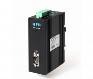
CAN Bus to Multi-drop Bus Fiber Optic Converter(New)
Configurable CAN to Multi-drop Bus Fiber Optic(FO) Converter
Description:
The FO-FIB-100BT CAN bus to fiber optic switch provide an optical Multi-drop bus or star network connection for CAN bus data interfaces on one or two, multi mode or single mode optical fibers. The CAN bus fiber optic switch has 1 CAN port and 2 fiber optic ports, CAN port is configurable via software.The CAN bus series units support both CAN 1.0 and CAN 2.0B CAN standards and are transparent to all high level protocols.The converter adopts the latest technology int world, so it can support very high baud rate,very long distance,very complex networks.
Product Features and Benefits:
Up to 1Mbps data rate(20km when it’s 1MB,New technology)Up to 6500 frames/second,with 1000 frames bufferingConfigurable CAN bus InterfaceMulti mode and single modeWith bufferingSingle fiber solution supported5 years warranty
Other Specifications:
|
Data |
|
|
Data Formats |
CAN1.0 ,CAN2.0 ,Device Net |
|
CAN Data Rate |
0-1Mbps |
|
Bit Error Rate |
<1 x 10-12 |
|
Connectors |
|
|
Data |
Screw Block Terminal |
|
Fiber |
ST, SC or FC (ST fitted as standard) |
|
Environmental |
|
|
Operating Temperature |
-30C---+70C |
|
Storage Temperature |
-40C---+90C |
|
Operating Humidity |
0-95% |
|
MTBF |
>100,000 Hours |
|
Optical |
|
|
Fiber |
Multi mode or single mode |
|
Wavelength |
850nm/1310nm |
|
Number of fibers |
8 or 4(WDM,Bi-Di) (2TX+2RX) |
|
Power |
|
|
Power Input |
+9-+40V DC |
|
Mechanical |
|
|
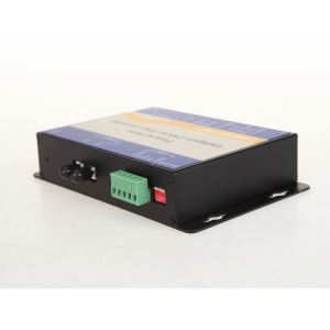
Dimensions |
156(W)×108(D)×33.6(H)mm Wall mount |
Ordering Information:
|
Model Number |
Description |
Port No. |
Fiber Mode |
Fiber Connector |
|
HFD-FO-CAN-P1M |
Fiber Optic Converter,Point to Point Link, Single Fiber(BI-DI), 2km,DIN Rail Mount |
1 CAN +1 FO |
Multi Mode |
ST/SC/FC |
|
HFD-FO-CAN-P2M |
Fiber Optic Converter,Point to Point Link, Dual Fiber, 2km,DIN Rail Mount |
1 CAN+1TX+1RX |
Multi Mode |
ST/SC/FC |
|
HFD-FO-CAN-P1S |
Fiber Optic Converter,Point to Point Link, Single Fiber(BI-DI), 20km |
1 CAN +1 FO |
Single Mode |
ST/SC/FC |
|
HFD-FO-CAN-P2S |
Fiber Optic Converter,Point to Point Link, Dual Fiber, 20km |
1 CAN+1TX+1RX |
Single Mode |
ST/SC/FC |
|
FO-FIB-100PT |
Configurable Fiber Optic Converter, Point to Point Link,Wall Mount |
1CAN+1TX+1RX |
Single Mode |
ST/SC/FC |
|
FO-FIB-100BT |
Configurable Fiber Optic Converter, Multi Drop Link,Wall Mount |
1CAN+2TX+2RX |
Single Mode |
ST/SC/FC |
|
FO-FIB-MIXED |
Configurable CAN Fiber Optic Switch, Point to point,Multi-drop,Star,Tree, Wall Mount |
2 CAN+2TX+2RX |
Single Mode |
ST/SC/FC |
|
SW-400T |
4 Port Configurable CAN BUS Switch, Wall Mount |
4 CAN |
||
|
BRIGE-200T |
Configurable CAN TO CAN Bridge |
2 CAN |
||
|
CANET-I |
1 Port CAN to Ethernet Converter |
1 CAN+1 TCP |
||
|
CANET-II |
2 Port CAN to Ethernet Converter |
2 CAN+1 TCP |
||
|
CAN-USB-I |
1 Port CAN to USB Converter |
1 CAN+1 USB |
||
|
CAN-USB-II |
2 Port CAN to USB Converter |
2 CAN+1 USB |
||
|
CAN-PCI-5001 |
1 Port CAN PCI Card |
1 CAN+1 PCI |
||
|
CAN-PCI-5002 |
2 Port CAN PCI Card |
2 CAN+1 PCI |
||
|
CAN-232 |
CAN to RS-232 Converter |
1 CAN+1RS232 |
||
|
CAN-485 |
CAN to RS-485 Converter |
1 CAN+1RS485 |
Devicenet Fiber Optic Converter
Devicenet / CAN Bus / Canopen Fiber Optic Extender Converter
he HFD-FO-DEV series DeviceNet fiber optic extender products.which used the most advanced technlogy in the world,can provide an optical point-to-point or bus network connection for DeviceNet data interfaces on one or two, multi mode or single mode optical fibers. The DeviceNet Point-to-Point Transmission units operate as the end or terminal points and provide an electrical connection and a two fibre optical connection. The units support CAN 1.0 and CAN 2.0 CAN standards, and CAN. And are transparent to all high level protocols.
This series DeviceNet Fiber Optic Converter is available in either wall mount, DIN rail or 3U chassis card configurations.
Product Features of the Devicenet fiber optic extender:
Multi mode and single mode
Single fiber solution supported
New technology: Long distance transmission(20km) when baud rate is at high speed, No cascading.
DIN Rail, Wall mount, rack or chassis configurations, Dual power supply
Data Protocol for option: DeviceNet, CAN Bus, CANOpen
Other specs of the Devicenet fiber optic extender:
| Data | |
| Data Formats | CAN1.0 ,CAN2.0 , Device Net,CAN Open |
| CAN Data Rate | 125K/250K/500K |
| Bit Error Rate | <1 x 10-12 |
| Connectors | |
| Data | Screw Block Terminal |
| Fiber | ST, SC or FC (ST fitted as standard) |
| Environmental | |
| Operating Temperat ure | - 3 0 C--- +70 C |
| Storage Temperature | - 40 C--- +85 C |
| Operating Humidity | 0- 95% |
| MTBF | >100,000 Hours |
| Optical | |
| Fiber | Multi mode or single mode |
| Wavelength | MM: 850nm, SM: 1310nm |
| Number of fibers | 2 or 1 |
| POWER | |
| Power Input | DC 9 ~ 30 V |
| Mechanical | |
| Dimensions | DIN Rail 124.5*43*88.5mm(H*W*D) |
Odering Information:
|
Model Number |
Description |
Fiber No. |
Fiber Mode |
Fiber Connector |
|
HFD-FO-DEV-P1M |
Point to point Link,Single Fiber(BI-DI), 2km |
1 |
Multi Mode |
ST/SC/FC |
|
HFD-FO-DEV-P2M |
Point to point Link,Dual Fiber, 2km |
2 |
Multi Mode |
ST/SC/FC |
|
HFD-FO-DEV-P1S |
Point to point Link,Single Fiber(BI-DI), 20km |
1 |
Single Mode |
ST/SC/FC |
|
HFD-FO-DEV-P2S |
Point to point Link,Dual Fiber, 20km |
2 |
Single Mode |
ST/SC/FC |
|
HFD-FO-DEV-M2M |
Multi Drop Bus Link,Dual Fiber(BI-DI), 2km |
2 |
Multi Mode |
ST/SC/FC |
|
HFD-FO-DEV-M4M |
Multi Drop Bus Link,4 Fiber, 2km |
4 |
Multi Mode |
ST/SC/FC |
|
HFD-FO-DEV-M2S |
Multi Drop Bus Link,Dual Fiber(BI-DI), 20km |
2 |
Single Mode |
ST/SC/FC |
|
HFD-FO-DEV-M4S |
Multi Drop Bus Link,4 Fiber, 20km |
4 |
Single Mode |
ST/SC/FC |
CAN to Fiber Optic Router Made by BE Plays a Role in Substation Automation System in Europe
CAN to Fiber Optic Router Made by BE Plays a Role in Substation Automation System in Europe. The product made by BE(Bueno Electric) works mainly as the router in this SAS system, the router has 6500 frames/second buffer/second and the buffer can be removed automatically in the nominated time to avoid the data jam. The router supports multi ways of communication such as star,tree,multi-drop bus and so on.

BE's CAN Bus to Fiber Optic Converter Application in Film Motion Control System
BE's CAN Bus to fiber optic converter successfully installed in DARBY FILM's Motion Control Systems.
Darby Film is based out of the Toronto area but Darby has worked throughout Canada, South America and much of Europe. Darby’s equipment knowledge and dedication to making your job a success shows in his long list of repeat clientèle.With the help of CAN Bus fiber optic converter, the motion film system controlled by PLC which is based on CAN protocol can strengthen the filming distances to 2km.
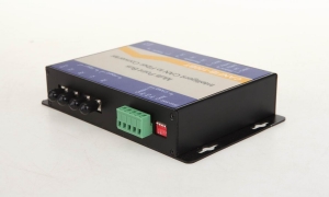
CAN Bus Fiber Optic Converter
CAN Bus Fiber Optic Converter(New Technology)
Model: FO-FIB-100PT
Description:
The CAN Bus series products provide an optical point-to-point or bus network connection for CAN bus data interfaces on one or two, multi mode or single mode optical fibers. The CAN Bus Point-to-Point Transmission units operate as the end or terminal points and provide an electrical connection and a two fiber optical connection. The units support CAN 1.0 and CAN 2.0 CAN standards, and Device Net. And are transparent to all high level protocols.It adopts the latest technology in the world,it can be transmitted to 20Km when it's at the baud rate of 1MB(6500 frames).Product Features
Up to 1Mbps data rate(Support high rate and long distance transmission)
Baud rate Configurable,by software and rotary button
Multimode and singlemode
Single fiber solution
Anti-stream: 1000 frames
Wall mount, rack or chassis configurations
Specification:
| Data | |
| Data Formats | CAN1.0 ,CAN2.0 , Device Net |
| CAN Data Rate | 0-1Mbps |
| Bit Error Rate | <1 x 10-12 |
| Connectors | |
| Data | Screw Block Terminal |
| Fiber | ST, SC or FC (ST fitted as standard) |
| Environmental | |
| Operating Temperat ure | - 3 0 C--- +70 C |
| Storage Temperature | - 40 C--- +85 C |
| Operating Humidity | 0- 95% |
| MTBF | >100,000 Hours |
| Optical | |
| Fiber | Multimode or singlemode |
| Wavelength | MM: 850nm, SM: 1310nm |
| Number of fibers | 2 or 1 |
| POWER | |
| Power Input | +9 to +40V DC |
| Mechanical | |
| Dimensions | 156(W)×108(D)×33.6(H )mm Wall Mount & DIN Rail |
Three Ways of Neutral Grounding in Power System
Effective grounding system (large current grounding system)
Small current grounding system (with ungrounded and arc - suppression coil grounding)
Resistance grounding system (including small resistance, medium resistance and high resistance)
Large current grounding system
For 110kV and above system. Single-phase earthing in the system, the other two relatively basic constant voltage, system overvoltage is low, good for 110 kv and above system restrain overvoltage, but this earth current is very big, the operation equipment is difficult to for a long time by the current, grounding voltage is relatively low, even to zero, the system voltage serious imbalance, many electrical equipment can't normal work, must be timely removal of ground. The large current grounding system requires that some of the main transformer be grounded and avoid the short-circuit current when the single-phase grounding is too large. These main changes must have a winding of the triangle wiring to form the zero sequence access and reduce the zero sequence impedance. The zero sequence impedance of the main variable is generally 1/3 of the positive sequence impedance, and the zero sequence impedance of the line is generally three times that of the positive sequence impedance.
The main transformer of the 220kV junction substation must be run in parallel. One of the main changes of 220kV side neutral point and 110kV side neutral point must be directly grounded, and other main variable neutral points are grounded through the gap. The advantage is that the zero sequence impedance of the 110kV side is stable, which is beneficial to the calculation and setting of the zero sequence value of the 110kV system. The protection scope of zero sequence overcurrent protection is very small and easy to maintain its step characteristics. The un220kv system provides stable zero sequence power supply and maintains the directivity and stability of the zero sequence protection of the 220kV system. The main variable 220kV side neutral point and 110kV side neutral point are protected by the gap protection.
The main variation of the 220kV load substation must be run separately. At this point, the 220kV side neutral point of the main variable must be grounded through the gap, and the 110kV lateral neutral point is fully grounded. The zero sequence current is provided by the main transformer in the 220kV system, and the zero sequence impedance is stable at 110kV. The main variable is 220kV side neutral point plus clearance protection, protection action jump off each side circuit breaker.
As the 220kV substation of the chain connection, its 220kV side bus is juxtaposed and has two power sources. Although the main variable column runs, it must have a primary variant of 220kV side neutral neutral ground, and the other main variable 220kV side neutral points are grounded through the gap. The lateral neutral point of 110kV must be directly grounded. The main variable is 220kV side neutral point plus clearance protection, protection action jump off each side circuit breaker.
The current operation of the 110kV transformer substation is divided and running, and its power side bus is single power supply. Therefore, the main variable 110kV side neutral point is grounded through the gap and no longer has clearance protection.
The 0.4kv system adopts large current grounding. For Y/Y0 wiring transformer, zero sequence impedance is very large. Although access to load more for single-phase load, since each load is small, will not necessarily cause the three-phase load current serious inconsistent (neutral current is less than 25% of the rated current), won't cause serious unbalanced three-phase voltage. However, when the circuit has a short circuit, the short circuit current is small, often unable to make the circuit breaker (air switch) jump off or fuse, causing the accident to expand, and in many cases the fire is formed. At this time, we should add the current protection to the transformer neutral point, and jump off the high voltage side circuit breaker. This is obviously complicated.
The transformer with delta/Y0 is used to overcome this disadvantage. But it is difficult to make the split-switch of oil filled transformer, especially with the load tapping switch. Although the transformer with zero sequence impedance is low, the voltage difference is not great when the three-phase current is unbalanced, but the current time of the neutral point is still not exceeding 60% of the rated current. For this purpose, 315kVA and the following small and medium sized transformers (especially oil filled transformers) use Y/Y0 wiring, and more than 315kVA transformers (especially dry transformers) are used in the delta/Y0 wiring.
At present, the power supply in large buildings adopts three-phase five-wire system, which is more than the original three-phase four-wire system. The ground and zero lines are connected at low voltage screens (or transformers) and are divided into two lines from the low voltage screen. The zero sequence can be connected to single-phase load, and there will be working current. The ground line will always be consistent with the earth because there is no working current. In order to ensure that the ground line is consistent with the earth's potential, it is necessary to repeat the grounding according to the regulations. And the zero line should not be further grounded, no longer connected to the ground wire, to avoid the production of working current in the ground. The metal enclosure of the electrical equipment shall be connected to the ground wire. When the electrical equipment is insulated and damaged, the circuit with the ground is formed, which causes the fuse or air switch to jump off when serious, and the shell potential is basically not raised, which poses no threat to the safety of the person.
Small current grounding system
When the neutral point of the system is completely ungrounded, whether it is overhead or cable, there are three relatively equal capacitors in normal operation. Because the tolerance is basically equal, the three relative voltage is basically equal, and the neutral voltage is very low (no more than 2% system rated voltage). When one of them to ground relatively lower voltage (metallicity grounding is zero), the ground relative to the voltage (metallicity grounding for the line voltage), ground of metallicity grounded current 3 times for each relatively capacitive current. If the voltage transformer is measured to the earth voltage in the system, the output voltage of the voltage transformer is rated voltage (the open triangle has a fixed connection). Depending on the voltage, it is possible to determine whether the system has a single-phase grounding. The system can be run for a long time due to the capacitor current only. Step but pick up location will be on the lives of those around produce very big threat (20 meters), in addition to all this system to monitor the voltage of the voltage transformer is designed according to adhere to eight hours. So find the location and remove it from the grid as soon as possible. An arc is produced when the ground contact is not strong. Since the arc current is not large, the arc cannot be maintained when the wire is far away from the place, and it will go out automatically. Intermittent arc current will cause the system to overvoltage, and the overvoltage will be limited to the allowable range of the system when the arc current is small.
When the system scale, single phase grounding capacitive current is also rapidly increasing, when the ground produces arc arc not extinguish, intermittent overvoltage caused by electric arc current system will exceed the scope of the system allows equipment insulation breakdown, accident.
In order to avoid to produce system cannot allow overvoltage, and make the ground arc is easy to go out, in a neutral point of reactor with a, make its produce inductive current offset ground capacitive current, make the earth point grounding current, over voltage amplitude decrease to the point of system is able to endure, and facilitate arcing. The reactor has been turned into an arc suppression coil. Inductor current is greater than the capacitive current system been compensation system, inductive current less than the system become less compensation systems of capacitive current, inductive current is equal to the system capacitive current become full compensation system. Without special measures, the full compensation system will be resonated when the system has no single phase grounding, and the system will not function properly. The uncompensated system may be close to full compensation when the system takes out a section of the line and is rarely used. The overcompensating system must make the operating current of the arc suppression coil exceed 10% of the system capacitance current at run time, and not exceed 10A, otherwise it will be very difficult to run.
Many system power supply is the transformer triangle wiring side, no neutral point can be led out. At this time, the system should install grounding transformer that provides zero sequence current. There are two kinds of earthing transformer: one is to introduce the neutral point of the transformer star connection winding, and the other one is the triangle; The other is a zigzag connection transformer (Z deformation). The capacitance of the grounding transformer is not less than that of the arc suppression coil.
There are usually multiple points, which generate different currents under phase voltage to correspond to different systems. Because we do not require single-phase grounding system to run for a long time, the design of the arc suppression coil in maximum current tap running for 2 hours, or the top oil temperature (oil filled) winding temperature (dry) shall not exceed the allowable values. Therefore, the arc suppression coil must be equipped with a thermometer that measures upper oil temperature (oil filling) or winding temperature (dry type) with alarm contact, and no station shall have a remote transmission device.
When the system changes (increase or decrease line length), the subsection of the arc coil should follow the regulation (overcompensation and undercompensation). At present, the power grid is developing and changing rapidly, so that many small current grounding systems are changing rapidly and manual operation is frequent. With the further expansion of the power grid, the capacitance current is also over 100A, and the working current of the arc coil is over 10% of the capacitance current of the system and the goal of not exceeding 10A is not achievable. So people developed automatic compensation suppression coil. Two simple introductions:
To be tuned (to set)
It consists of an arc coil with a split-switch, a single phase PT, a resistance cabinet with a short circuit switch and a controller. Before running short circuit switch in break-brake position, control cabinet after charged, in the arc suppression coil into a special frequency voltage, enclosed by single-phase PT and coil CT measurement of the neutral point voltage and capacitor current component, computing system capacitive current value. The controller will automatically adjust the arc suppression coil to the nearest connection with the capacitance current of the system. Because the loop has a resistor at this point, the resonance cannot occur. The controller keeps measuring the capacitance current of the system. When the system capacitance current changes, the controller automatically adjusts the arc suppression coil to be close to the system capacitor current. When the single-phase grounding system (PT open delta voltage reached more than 30 v), the controller will resistance with switch is short circuit, arc suppression coil offset currents can be ground capacitive current, ground current is small, can rapidly arcing. After the grounding of the system is restored, the controller is out of the switch and the resistance system resonated.
Methods two tracking
It consists of a transformer with short circuit coil, thyristor and eliminate harmonic device cabinets and controllers. The current of a coil is very small at the time of circuit opening, which is the empty current of the transformer. The current of a coil is the rated current of the extinction coil when the short circuit is short circuit. The guide Angle can adjust the short-circuit degree of the short-circuit coil and adjust the working current of the arc suppression coil. After the operation of the entire plant controller by constantly transformation thyristor conduction Angle, get a different point of working current coil, and measured the current point of neutral point voltage (open delta voltage), calculate the system capacitive current, and memory. When the capacitance current of the system changes, the controller can measure and change the memory at any time. When the system has a single-phase grounding (the voltage of the busbar PT opening triangle is above 30V), the thyristor guide Angle is rapidly activated by memory, and the capacitance current at the site is compensated close to zero. The arc can be extinguished quickly. After grounding of the system, thyristor was closed.
Resistance grounding system (including small resistance, medium resistance and high resistance)
The city grid is mainly cable. The characteristic is capacitive current is very big, often reach 100A above. The population density is very high, the single phase grounding voltage vulnerable personnel. So use the resistance grounded system. 10 kv neutral point to earth access 5-10 Ω resistance for the small resistance system, access to a few decades - 100 Ω resistance to resistance in the system, access to a few hundred - 1000 Ω resistance for high resistance system. The resistance grounding system when the single-phase grounding relative decline (metallicity grounding is zero), the ground relative to the voltage (metallicity grounding for the line voltage), ground current for capacitive current and the resistance of resistance current combined. After protection, the circuit breaker will disconnect from the system. As the resistance of the neutral point is larger, the overvoltage of single phase grounding increases gradually. In the Beijing area 10 kv system currently USES small resistance grounding system, neutral resistance for 10 Ω.
When the small resistance grounding system is running, the grounding resistance must not be out of operation, and the two grounding resistance shall not be run in parallel. At present, the 10kV system in Beijing is connected with the neutral point resistance. There are two ways to connect to earth. One way is to access the bus. This method is more complicated in reverse operation. Before the 10kV busbar is charged, the neutral resistance is put into the main switch. The main switch of 10kV is removed after the neutral resistance protection action, and 10kV main switch auxiliary contact to remove the neutral point resistance switch. Therefore, in the 10kV main switch auxiliary contact circuit, the pressure plate must be loaded, and the unmanned substation should be connected with a remote contact. The other way is to take the main transformer 10kV lead, only to add the single CT and protection, no longer the circuit breaker (separate grounding and resistance can be installed near the main transformer). This method is to remove the transformer when the three coil transformer adopts this connection, and the power failure of the middle voltage side (self-investment) can be made.
The ground current is mainly the resistance when the small resistance grounding system is grounded. Therefore, determining the current size can determine whether the protective element is grounded and generally used for flow protection. When the fixed value is easy to be interfered with capacitance current, the Beijing area requires that the capacitance current of the component is less than 30A (except for the reverse operation process) at any time. Small resistance grounding system of distribution transformer shell (oil filled) or iron core and outer garment (dry), if the grounding resistance is greater than 4 Ω must be separated from neutral.