
Super User
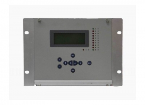
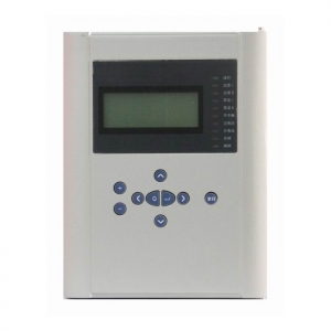
Digital Standby Power Automatic Switching Device

Standby Power Automatic Switching Device(For all voltage levels)
BEPR-851U digital standby power automatic switching device. The realization of automatic throw-over function adopts the graphic logically programmable mode, which would flexibly realize each automatic throw-over scheme, applicable for the control of the automatic throw-over device at various voltage levels.
Features and Benefits
- All English character LCD display, and clear and easy man-machine interface.
- The precision of the selected measuring modules (including KWH metering ) can reach to the class 0.5.
- To provide access to the accumulated pulse-degree side.
- High speed Ethernet interface is provided to integrated the IEC 870-5-103 standard communication protocol.
- High precision clock chips are used. The GPS time checking circuit is provided to realize the clock synchronism of the whole system.
- High speed Ethernet interface is provided to integrated the IEC 870-5-103 standard communication protocol.
- The core of CPU, the protection functional module is the powerful 32-bit micro- processors with large capacity RAM and Flash Memory. They are powerful to process data, perform logic calculation and store information. 8 to 50 recorded reports and 1000 events can be recorded. These information will not be lost even in power interruption.
Complete functional configuration
This product is internally integrated with many kinds schemes, such as automatic throw-over devices for substation or bridge switches, line switches, and transformers, etc. The user is only required to select the connection mode, and set the simple rated values settings, to reach the scheduled requirements. Special automatic throw-over schemes can be realized fast and reliably. Current and voltage protection can be loaded.
- Telemeter: I Ia,Ib,Ic,Ua,Ub,Uc,P,Q,f and other analog telemetry
- Telecontrol: Division and the normal remote control circuit breaker
- Telesignal:16way telesignalling open into the volume of the collection, installation of remote signal deformation, events, letters and other remote
- Remote pulse: 2-way electric-degree pulse input
- Out: Device has a 13 way out, of which 10 road trip because of the export-driven relay, 3-way signal drive for the notice of police.
- GPS time-checking
Technical Parameters
Rated parameters
Rated DC voltage: 220V or 110V (please specify in order),
permissive error: -20%~+10%.
Rated AC data:
a) Voltage 100V
b) Current 5A or 1A
c) Frequency 50Hz
Power consumption
a) DC power circuit Under normal work: no more than 25W
During operation: no more than 40W
b) AC voltage circuit No more than 0.5VA for each phase
c) AC current circuit when the rated current is 5A: no more than 1VA for each phase.
State vector level
The input state vector level of CPU and communication interface module
24V(18 V~30V)
GPS time synchronization impulse input level
24V(18 V~30V)
CPU output state variable (photo-coupling output)
Permitted level 24V(18 V~30V)
Driving capability 150mA
Main technical performance
Sampling circuit precise working range (10% error)
Voltage:0.4 V~120V
Current:0.08In~20In
Contact capacity
Signal circuit contact load: 400VA
Signal circuit contact arc break: 60VA
Sub-section tripping current and closing current
CB tripping current 0.5A~4A(please specify in the order)
CB closing current 0.5A~4A(please specify in the order)
Precision of various of component
Current component: ≤±5%
Voltage component : ≤±5%
Time component: ≤±20ms
Operation time (include relay inherent time)
Inherent operation time of transient output: ≤50ms
Insulation capability
Insulation resistance
The insulation resistance values between the charged parts and in charged parts, racks as well as irrelevant electrical circuits are measured by 500V megger and under normaltest atmospheric conditions, the resistance values of the various circuit at all levels are not lower than 50MΩ .
Media intensity
Under normal test atmospheric conditions, the device can tolerate the frequency 50Hz, signal input terminal to ground voltage, 500V, other circuit to ground voltage 2000V, 1min power-frequency withstand voltage test, without breakdowns, flashovers and element damages. During the test, when the voltage is applied at any tested circuit, all the other circuits are interconnected and grounded equip otentially.
Impulse voltage
Under normal experiment atmospheric conditions, the power input circuit, AC input circuit, output contact point circuit to ground, and all the circuits are able to endure short-time standard lightning impulse voltage test of 1.2/50μs, with open-circuit test voltage of 5kV.
Humidity and heat resistance performance
This device can endure the constant humidity and heat test regulated in GB/T
7261-2000, chapter 20, with highest test temperature +40℃, hightest humidity 95%,and test time of 48h. Within two hours after the completion of test, according to the requirements in 2.3.1, among the outside uncharged parts of each conductive circuit, the casing and irrelevant electrical circuits, the insulation resistance is measured, and it is no less than 1.5MΩ. The medium voltage withstand intensity is not below the 75% of voltage amplitude in medium intensity test.
Electromagnetic compatibility (EMC) capability
Electrostatic discharge immunity test
This device can endure the electrostatic discharge immunity test Class IV stipulated in GB/T 17626.2-1998.
Radiated Radio-frequency electromagnetic field immunity test
This device can endure the radiated, radio-frequency, electromagnetic field immunity test Class III stipulated in GB/T 17626.3-1998.
Electrical fast transient/burst immunity
This device can endure the electrical fast transient/burst immunity test Class IV stipulated in GB/T 17626.4-1998.
Surge immunity test
This device can endure the surge immunity test Class III stipulated in GB/T 17626.5-1999.
Immunity to conducted disturbances, induced by radio-frequency fields
This device can endure the immunity to conducted disturbances, induced by radio-frequency fields test Class III stipulated in GB/T 17626.6-1998.
Power frequency magnetic field immunity test
This device can endure the power frequency magnetic field immunity test Class V stipulated in GB/T 17626.8-1998.
Pulse magnetic field immunity test
This device can endure the pulse magnetic field immunity test regulated Class V stipulated in GB/T 17626.9-1998.
Damped oscillatory magnetic field immunity test
This device can endure the damped oscillatory magnetic field immunity test Class V stipulated in GB/T 17626.10-1998.
Oscillatory waves immunity test
This device can endure the oscillatory waves immunity test Class IV stipulated in GB/T 17626.12-1998.
Radiated emission limited value test
This device has passed the radiated emission limited value test A stipulated in GB 9254-1998
Mechanical performance
Vibration
This device can endure the grimness vibration duration test of severity Class I stipulated in 16.3 of GB 7261-2000.
Impact
This device can endure the impact duration test of severity Class I stipulated in 17.5 of GB 7261-2000.
Collision
This device can endure the collision test of severity Class I stipulated in Chapter 18 of GB 7261-2000.
Environment conditions
a) Environment temperature:
Work: -20℃~+55℃(as required in the contact)
Storage: −25℃~+70℃, no energized variables are applied at the limit value and no irreversible changes occur. The device can normally operate when the temperature recovers.
b) Relative humidity: The wet month on the mean maximum relative humidity was 90%, At the same time of the month on average minimum temperature of 25 ℃ and the surface without any dew. The highest temperature of + 40 ℃, relative humidity of the mean maximum no more than 50%.
c) Atmospheric pressure: 86kPa~106kPa(lower than 2km at the altitude above sea level).
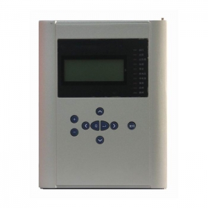
Automatic Quasi-synchronizing Device
Automatic Quasi-synchronizing Device
Include 6 channels of Automatic Quasi-synchronizing Device,the main function is frequency modulation,voltage regulation and quasi-synchronizing judgement.
Product Description:
Product model: BEPR-511U Automatic Quasi-synchronizing Device
Product Feature and Benefits:
- Man-machine interface friendly, operation.
- The precision of the selected measuring modules can reach to the class 0.5.
- Configured with plenty of switch quantity input, convenient external tele-siginal access
- Equipped with high precision clock chip, and equipped with GPS hardware clock synchronization circuits , is advantageous for the whole system clock synchronization
- Equipped with high speed Ethernet communication interface, and integrate the IEC 60870-5-103 standard communication protocols
Product Configuration and Functions:
- One device can control up to 6 generators or 6 lines for paralleling-in.
- After settings and control words have been set up, only paralleling points are needed to be selected for each time of connecting into network.
- Multiple closing exits form the final closing exit via “And” logic relation.
- CB closing time angle difference is less than 0.5°.
- Three paralleling modes are supported, that is, difference frequency paralleling, common frequency paralleling, and no-voltage paralleling.
- Actuating can be done through digital input actuation
- Having the function of automatic angle turning, therefore, angle turning transformer is not required. Turning angles can be selected among 30 º leading,0 º, and 30 º lagging.
- The leading time is measured by using the CB auxiliary contact input signals.
- For the type of device which is used for generator units, automatic frequency regulating and automatic voltage regulating can be performed, and therefore, closing time is shortened.
- The automatic frequency and voltage regulating functions for each paralleling point can be enabled or disabled by using the control word.
- When common frequency occurs during the generator paralleling-in process, the device can automatically give out acceleration control commands.
- During the paralleling process, if the voltage becomes greater or less than the setting, the device will automatically block the voltage regulating function, and at the same time, closing will be blocked.
- During the paralleling process, if the frequency becomes greater or less than the setting, the device will automatically block the frequency regulating function, and at the same time, closing will be blocked.
- Having the functions of frequency difference (ΔF) blocking and voltage difference (ΔU) blocking closing.
- Chinese language or English language LCD display, easy for monitoring, setting and modifying.
- AC rated voltage: 100V or 57.74V(optional)
Technical Spefications:
Rated parameters
Rated D.C. voltage : 220V or 110V ( as required )
Rated A. C. dat:
a) Phase voltage 100 / V
b) Line extraction voltage 100 or 100 / V
c) Rated frequency 50 Hz
Power consumption :
a) D.C circuit normal : not larger than 25W
operation: not larger than 40W
b) A.C voltage circuit not larger than 0.5VA for each phas
Status voltage :
Input voltage to CPU and signal interface 24V (18V~ 30V )
The GPS clock pulse input level 24V (18V~ 30V )
Output status (optic coupled output ) permissive voltage 24V ( 18V ~ 30V )
driving power 150 mA
Main technical performance
Operating range for sampling circuits (5% tolerance )
Voltage: 0.4V~120V
Contact capacity
current capacity of the signal circuit contact 400VA
arc-breaking capacity of the signal circuit contact 60VA
Tripping and closing current
CB tripping current 0.5A~4A ( as required )
CB closing current 0.5A~4A ( as required )
Precision of elements
voltage element less than ± 5%
Inspection synchronization angle less than ± 1°
Timing element less than ± 20 ms
Frequency deviation less than ± 0.02 Hz
Slip difference value less than ±5%
Precision of measuring circuits for analog variables monitoring device equipped with the special measurement sub-module :
voltage : class 0.2
Insulation property
Insulation resistance
Insulating resistance between active parts and passive parts or casings and electrically unrelated circuits is measured by the 500V megaohmmeter to be not less than 50MΩ for the various circuits at different levels under the normal test atmospheric conditions.
Strength of insulating media
Under the normal test atmospheric conditions, the protection can withstand the power frequency withstand voltage test of 50 Hz, 2000V and 1 min without any breakdown flashover and element damages. During the test, as a voltage is applied at any tested circuit, the other circuits are inter connected and grounded with an equivalent potential.
Impact voltage
Under the normal test atmospheric conditions, the short-duration impact voltage test of 1.2 /50 µs standard lightning wave is done on the power input circuits. AC input circuits, output contact circuit to the ground and between circuits. The open test voltage is 5 kV.
Heat and moisture-proof performance
The protection can withstand the heat and moisture-proof test stipulated in GB/T 2423.9. The alternating heat and moisture-proof test is to be done at the highest temperature +40℃±2℃, the maximum humidity(93±3)%, for 48 hrs and at a cycle of 24 hrs. In 2 hrs before the test is finished, according to the requirements in section 2.3.1, the insulation resistance between the conducting circuits and external passive metals and casings and electrically unrelated parts are measured to be not less than 1.5 MΩ, the withstand voltage strength of the media not less than 75% of the voltage magnitude of the media strength test stipulated in the section 2.3.2.
Anti-electromagnetic interference
Electrostatic discharge
By GB/T 17626.2 1998 standard electrostatic discharge anti-interference level 4 test.
Radio frequency electromagnetic field radiation anti-interference
By GB/T 17626.3 1998 standard Radio frequency electromagnetic field radiation anti-interference level 3 test.
Electrical fast transient pulse group anti-interference
By GB/T 17626.4 1998 standard Electrical fast transient pulse group anti-interference level 4 test.
Surge immunity (impact)
By GB/T 17626.5 1998 standard Surge immunity (impact) anti-interference level 3 test.
Rf induction conduction disturbance degrees
By GB/T 17626.6 1998 standard Rf induction conduction disturbance degrees anti-interference level 3 test.
Power frequency magnetic field anti-interference
By GB/T 17626.8 1998 standard ower frequency magnetic field anti-interference level 5 test.
The pulse magnetic field anti-interference
By GB/T 17626.9 1998 standard The pulse magnetic field anti-interference level 5 test.
Damping oscillating magnetic field anti-interference
By GB/T 17626.10 1998 standard Damping oscillating magnetic field level 5 test.
Oscillation wave anti-interference
By GB/T 17626.12 1998 standard Oscillation wave anti-interference level 4 test.
Radiation emission limit test
By GB 9254-1998 standard Radiated emission limits A class test.
Mechanical performance
Vibration
The protection can withstand the impact duration test of the severity class I stipulated in the section 16.2 of GB/T 7261.
Impact
The protection can withstand the impact duration test of the severity class I stipulated in the section 17.4 of GB/T 7261.
Crash
The protection can withstand the impact duration test of the severity class I stipulated in the Chapter 18 of GB/T 7261.
Environment conditions
a) Ambient temperature :
operation : -20ºC~ +55ºC .
storage : -25ºC ~ +70ºC , no exciting variables are applied at the limit value and no irreversible changes
occur. The protection will operate normally after the recovery of temperature.
b) Relative humidity : maximum monthly average humidity 90 % at the lowest temperature of 25ºC, (no
condensation ). At the highest temperature of +40ºC, maximum humidity must not be
over 50 %.
c) Atmospheric pressure : 86 ~ 106 kPa ( relative altitude above sea level is less than 2 km ).
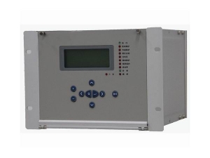
Digital Comprehensive Monitoring Device
Digital Comprehensive Measurement and Control Device
BEPR-860 Series Digital Monitoring Device is a dispersed unit equipment-oriented monitoring device. It takes the Motorola MCU as its core processor. The internal part of each unit consists of the multi-CPU modules linked by the reliable and fast CAN bus. The functions of the various submodules of the device are allocated as follows: intelligent digital variable acquisition module (hereafter referred as DI), Intelligent AC acquisition modules (those containing 4TV and 4TA are hereafter referred as AC; those containing 8TA as AC-I, those containing 8TV as AC-U), intelligent temperature DC acquisition module (DC), intelligent control module (OUT), intelligent digital input and output module (DIO), non-intelligent AC input module (NAC), non-intelligent output module(NOUT), voltage parallel module (VP) network interface module(COMM) and other selectable module. The main module (CPU) is responsible for the management and collection of the information and configuration of the various submodules. Those special functions, e.g., synchronism, remote/ local, etc. are detected and discriminated by the main module. The functions of the module DI include the acquisition of the configurable switching variables, acquisition of the pulses and acquisition of the codes signals, etc.. The functions of the AC module include the acquisition of current, voltage, active power, reactive power, power factor, active electric energy and reactive electric energy. The DC modules acquire the external weak DC input variable, which may be the temperature or the DC voltage variables output by the DC transducer. The OUT module can implement the telecontrol / teleadjust functions. The DIO module can execute the telesignal, telecontrol / teleadjust functions to realize the function of the telesignal blocking telecontrol and slip blocking functions, etc..
There are two sizes for the cubicles of the monitoring device: 19 inch 4U standard cubicle and 19/2 inch 4U standard cubicle. A Power supply module and a main module for administration are mounted within each kind of cubicle and their positions in the cubicle are relatively fixed. They occupy the width of 60mm (for 19 inch cubicle, and 50mm for 19/2 inch cubicle) and 30mm. The width of the other modules is 30mm except the AC module whose width is 60mm. Moreover, the modules of 30 mm are inter-chargeable in the various slots of the cubicles. Their positions and configurations are relatively flexible. The main module for administration has the capability for a certain capacity of the switching variable acquisition (8-circuirt) analog variable acquisition (8-circuit) and signal output (8-circuit), which is usually used to drive the 8-circuit null contact output of the non-intelligent output module. If the function of synchronism is required, the NAC and NOUT modules can be configured at the left and right sides of the main module for administration to let the main module execute the discrimination and the command output of the synchronous closing function. The plugging-in position of these two modules is relatively fixed in their application.
Fig. 1-1 shows the schematic diagram for the configuration of the 19/2 inch cubicle (back view). Fig.1-2 shows that for 19 inch cubicle (back view). The AC module in the figure occupies the position for two DI (or DC, OUT, DIO) modules in which two DI /DC / OUT / DIO modules can be inserted. The position of DI / DC / OUT / DIO in the figure can be interchanged or increased or decreased or in other capacity allocation modes. The slots of any two continuous DI / DC / OUT / DIO modules can be inserted by AC modules; the various input variables of the DI modules themselves can be also let as the inputs of the different natures. All these modes make the configuration of the device very flexible. But we suggest that the user’s requirements be incorporated in the typical configuration schemes provided by our company. This is not only feasible for the administration of out manufacture, but also will realize the specification of the user’s administration. (Attention: Fig.1-1 and 1-2 are only used as the reference for configuration and do not represent the actual dimensions and they are not the sole mode for configuration.)
Capacities of the various modules: 20-circuits of digital variable input for DI module, 12-circuits of input for DC module, 10-circuits of open contact output for OUT module (the output of the 11th circuit is output jointly with that of the 9th circuit. For the control of circuit breakers and isolator, starting from the output null contact of the first circuit, the order is recommended to be arranged as open, close, open, close…), 11 circuits digital variable input and 5 circuits open contact output for DIO module, 4 circuits of current and 4 circuits of voltage for AC module, 8 circuits of current for AC-I module, 8 circuits of voltage for AC-U module, 8 circuits of open contact output (there is a pair of jointly-operated contact output for the first and third circuit respectively), 4 circuits of current and 4 circuits of voltage for NAC module.
Table 1-1 Simplified list of the parameters for the modules of BEPR-860 Series Device
| Name of module |
Slot occupied |
Occupied width (mm) |
Inserting position not fixed |
Selectable or necessary | Is it an intelligent module | Terminals from module(note) | Acquired data capacity | Output data/contact |
| AC |
√ (occupied) |
2*30 |
√ (not fixed) |
selectable |
√ (yes) |
10+12I |
4*U, 4*I |
I,U,P,Q, COS,+EP, +EQ, -EP, -EQ |
| AC-I | √ | 2*30 | √ | Selectable | √ | 24I | 8*I | I |
| AC-U | √ | 2*30 | √ | Selectable | √ | 16 | 8*U | UAC |
| DC | √ | 30 | √ | Selectable | √ | 14 | 12*DC | UDC |
| DI | √ | 30 | √ | Selectable | √ | 22 |
20*DI/ coding/PI |
DI, SOE, coding, PI |
| DIO | √ | 30 | √ | Selectable | √ | 22 | 11*DI |
(ditto), 5*digit-out |
| OUT | √ | 30 | √ | Selectable | √ | 22 | - | 10*digit-out |
| VP | √ | 30 | √ | Selectable | × | 22 | - |
10*N.O., 1*N.C. |
| NAC | √ | 2*30 | × | Selectable | × | 10+12I |
4*U, 4*I |
I, UAC ,f |
| NOUT | √ | 30 | × | Selectable | × | 22 | - | 8*digit-out |
| CPU | √ | 30 | × | Necessary | √ |
12+2* RJ45 |
8*DI, 1GPS |
DI,SOE, data of various submodules |
| POWER | √ | 60 or 50 | × | Necessary | × | 12 | - | - |
| MMI | × | - | × | Necessary | √ | - | - | - |
| COMM | √ | 30 | √ | Selectable | √ |
3*RJ45, 2*DB9 |
- |
(network/ communication: interface/ conversion/ rout/printing server) |
Note 1: “I” denotes current terminal in this list. “DB9” denotes 9-pin serial interface. “RJ45”denotes Ethernet twin-twisted interface. Others are “MSTB2, 5” Series Phoenix terminals.
Technical Parameters
Rated parameters
Rated DC voltage input: 220V or 110V(indicate in ordering)Rated DC voltage output: +5V, ±12V, +24V(1), +24V (2)
Rated AC data:
AC voltage: 100V, 100 /V
AC current: 5A or 1A (indicate in ordering)
Rated frequency 50Hz /60Hz
Power consumption
DC circuit: 19/2 inch cubicle: <30W;
19 inch cubicle: < 60W
AC voltage circuit: ≤0.5VA / phase
AC current circuit: ≤0.75VA / phase
Status variables, pulsing variable level 24V (18V-30V)Pulse width: ≥10ms (This parameter is related with the setting up or the time constant for the filtering of the pulsing variable inputs and can be set.)
Main technical property
AC circuit measuring range
Voltage: 0~120V
Current: 0~1.2In
Contact capacity
Control output contact current-carrying capacity: 10A (250V AC / DC)
Control output contact breaking capacity: 10A (30V DC); 10A (250V AC)
Accuracy of the analog variable measuring circuit
AC current, voltage: 0.2 class
Power, KWH: 0.5 class
Temperature, DC: 0.2 class
Event of sequence records resolution: ≤ 1ms
Overload capability
AC current circuit: continuous operation at 2 times the rated current
Continuous operation for 10s at 10 times the rated current
Continuous operation for 1s at 40 times the rated current
DC power supply circuit: continuous operation at 80%~115% the rated voltage
Response time for upward transmitted data:
Telesignaling position-variation < 1s;
Telemetering varied data < 2s
Insulation property
Insulation resistance
Insulating resistance between active parts and passive parts or casings and electrically unrelated circuits is measured by the 500V megaohmmeter to be not less than 50MΩ for the various circuits at different levels under the normal test atmospheric conditions.
Strength of insulating media
Under the normal test atmospheric conditions, the protection can withstand the power frequency withstand voltage test of 50 Hz, 2000V and 1 min without any breakdown flashover and element damages. During the test, as a voltage is applied at any tested circuit, the other circuits are interconnected and grounded with an equivalent potential.
Impact voltage
Under the normal test atmospheric conditions, the short-duration impact voltage test of 1.2 /50 µs standard lightning wave is done on the power input circuits. AC input circuits, output contact circuit to the ground and between circuits. The open test voltage is 5 kV.
Heat and moisture-proof performance
The protection can withstand the heat and moisture-proof test stipulated in the GB/T2423.9. The test is done at the temperature of +40ºC±2ºC, the related humidity of (93±3)%. The constant heat and moisture-proof test is done for 48 hrs. In 2 hrs before the test is finished, according to the requirements in section 2.3.1, the insulation resistance between the conducting circuits and external passive metals and casings and electrically unrelated parts are measured to be not less than 1.5 MΩ, the withstand voltage strength of the media not less than 75% of the voltage magnitude of the media strength test stipulated in the section 2.3.2.
Anti-electromagnetic interference
Pulse interference
The protection can withstand the interference test of 100 kHz and 1MHz at the severity class III, i.e. decaying oscillation wave at the test voltage of 2500V common mode and 1000V differential mode stipulated in GB/T14598.13-1998. As the pulsing group interface is applied, the protection will not misoperate or refuse to operate. In the test, the protection’s properties are still consistent with the stipulations in the technical specifications.
Electrostatic discharge
The protection can withstand the class III (8kV for air discharge, 6kV for contact discharge) electrostatic discharge test stipulated in the Standard IEC255-22-2.
Mechanical performance
Vibration
The protection can withstand the vibration duration test and vibration response capability test of the severity class I stipulated in the IEC 60255-21-1: 1988.
Impact
The protection can withstand the impact duration test and impact response test of the severity class I stipulated in GB/ T 14537-1993.
Collision
The protection can withstand the collision test of the severity class I stipulated in the Section 4.3 of GB / T 14537-1993.
Environment conditions
Ambient temperature :
operation : -5ºC~+ 40ºC.
storage : -25ºC~+70ºC, no exciting variables are applied at the limit value and no irreversible changes occur. The protection will operate normally after the recovery of temperature.
Relative humidity: maximum monthly average humidity 90% at the lowest temperature of 25ºC, (no condensation ). At the highest temperature of +40ºC, maximum humidity must not be over 50 %.
Atmospheric pressure: 80~110 kPa ( relative altitude above sea level is less than 2 km ).
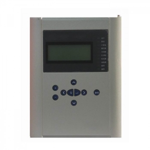
Line Protective Relay
Line Protective Relay Device
The BEPR-811U Digital Line Protection is a packaged line protection basically configured of current, voltage and 3-phas e reclosing relays. It is applicable for the line and Busbar at the voltage levels of 66kV or less.
The protection device adopts perfect software synchronous sampling technology, control on both sides of the sample synchronization error less than 4 degrees, improve the differential protection action precision.
Two fundamental CPU modules are provided. One of them is a relay constructed of the 32-bit microprocessors. This unit is fitted with the large volume RAM and Flash Memory, and is powerful enough to carry out data processing, logic calculation and information storage. Another CPU is a general man-machine interface constructed of a single-chip computer. Two CPUs are independent to each other. All protection and automation functions are implemented by software. The logic relations in protection comply with the principle of “four unification ”
Product Features and Benefits:
- All English character LCD display, and clear and easy man-machine interface.
- The precision of the selected measuring modules (including KWH metering ) can reach to the class 0.5.
- To provide access to the accumulated pulse-degree side.
- High speed Ethernet interface is provided to integrated the IEC 870-5-103 standard communication protocol.
- High precision clock chips are used. The GPS time checking circuit is provided to realize the clock synchronism of the whole system.
- High speed Ethernet interface is provided to integrated the IEC 870-5-103 standard communication protocol.
- The core of CPU, the protection functional module is the powerful 32-bit micro- processors with large capacity RAM and Flash Memory. They are powerful to process data, perform logic calculation and store information. 8 to 50 recorded reports and 1000 events can be recorded. These information will not be lost even in power interruption.
Complete protection function configuration
Table 1 Types and functional configuration of this series products
| Function | BEPR- 811U | ||||
| Phase current differential | |||||
| P-p directional current zones II, III | √ | ||||
| Zero-sequence directional current zone II, III | √ | ||||
| Current inverse time-limit | √ | ||||
| Zero-sequence inverse time-limit | √ | ||||
| Directional blocking | √ | ||||
| Voltage blocking | √ | ||||
|
3-phase reclosing |
Synchronism or no voltage | √ | |||
| Asynchronism | √ | ||||
| 2nd shot reclosing | √ | ||||
| acceleration | Pre-acceleration | √ | |||
| Post-acceleration | √ | ||||
|
Manual closing acceleration |
√ | ||||
| LF, LV load shedding | √ | ||||
| Overload | √ | ||||
| Telecontrol function pressure plate | √ | ||||
| Telemeter | Measurement TA | alternative use | |||
| Protection TA | alternative use | ||||
| Telesignal | alternative use | ||||
| Telecontrol | alternative use | ||||
| KWH | KWH measurement | √ | |||
| GPS time-checking | √ | ||||
| False blocking prevention | √ | ||||
| Remote management | √ | ||||
Monitoring
Telemeter:Ia, Ib, Ic, Ua, Ub, Uc, P, Q, f and other analog telemetry
Telecontrol:Division and the normal remote control circuit breaker
Telesignal:16way telesignalling open into the volume of the collection, installation of remote signal deformation, events, letters and other remote
Remote pulse: 2-way electric-degree pulse input
Out: Device has a 13 way out, of which 10 road trip because of the export-driven relay, 3-way signal drive for the notice of police.
GPS time-checking
Technical Parameters
Rated parameters
Rated D.C. voltage : 220V or 110V ( as required )
Rated A. C. data
a) Phase voltage 100 / V
b)Tapped voltage of the line: 100V or 100 /V
c) A.C current 5A or 1A( as required )
d) Rated frequency 50 Hz
Power consumption :
a) D.C circuit normal : not larger than 25W
operation: not larger than 40W
b) A.C voltage circuit not larger than 0.5VA for each phase
c) A.C current circuit not larger than 1VA for each phase (for 5A rating )
not larger than 0.5VA for each phase ( for 1A rating )
Status voltage :
Input voltage to CPU and signal interface 24V (18V~ 30V )
Input voltage to GPS time checking 24V (18V ~ 30V )
Output status (optic coupled output ) permissive voltage 24V ( 18V ~ 30V )
Driving power 150 mA
Main technical performance
Operating range for sampling circuits (10% tolerance )
voltage : 0.4V ~120V
current : 0.08In ~ 20In
Contact capacity
current capacity of the signal circuit contact 400VA
arc-breaking capacity of the signal circuit contact 60VA
Tripping and closing current
CB tripping current 0.5A, 1A, 1.5A, 2A, 2.5A, 3A, 3.5A, 4A ( as required )
CB closing current 0.5A, 1A, 1.5A, 2A, 2.5A, 3A, 3.5A, 4A ( as required )
Precision of elements
current elements <± 5%
voltage element <± 5%
synchronism-check angle: <± 1°
timing element <± 20 ms
frequency deviation: <±0.02Hz
slip rated value: <± 5%
Operating Time of the complete protection ( including time needed by relay )
Fixed operating time of the instantaneous zone when measured at 1.2 times of setting value: not longer than 40 ms
Precision of measuring circuits for analog variables monitoring device equipped with the special measurement sub-module :
current, voltage : class 0.2
power, KWH : class 0.5
Insulation property
Insulation resistance
Insulating resistance between active parts and passive parts or casings and electrically unrelated circuits is measured by the 500 megaohmmeter to be not less than 50MΩ for the various circuits at different levels under the normal test atmospheric conditions.
Strength of insulating media
Under the normal test atmospheric conditions, the protection can withstand the power frequency withstand voltage test of 50 Hz, 2000V and 1 min. without any breakdown flashover and element damages. During the test, as a voltage is applied at any tested circuit, the other circuits are inter connected and grounded with an equivalent potential.
Impact voltage
Under the normal test atmospheric conditions, the short-duration impact voltage test of 1.2 /50 µs standard lightning wave is done on the power input circuits. AC input circuits, output contact circuit to the ground and between circuits. The open test voltage is 5 kV.
Heat and moisture-proof performance
The protection can withstand the heat and moisture-proof test stipulated in the Chapter 20, GB/T 7261. The alternating heat and moisture-proof test is to be done at the highest temperature +40ºC, the maximum humidity 95%, for 48 hrs and at a cycle of 24 hrs. In 2 hrs before the test is finished, according to the requirements in section 2.3.1, the insulation resistance between the conducting circuits and external passive metals and casings and electrically unrelated parts are measured to be not less than 1.5 MΩ, the withstand voltage strength of the media not less than 75% of the voltage magnitude of the media strength test stipulated in the section 2.3.2
Electromagnetic compatibility properties
Electrostatic discharge anti-interference
The protection conforms to the standard GB/T17626.2-1998, electrostatic discharge anti-interference test class 4
RF electromagnetic field radiation anti-interference
The protection conforms to the standard GB/T17626.3-1998, RF electromagnetic field radiation anti-interference test class 3
Electric fast transient pulse group anti-interference
The protection conforms to the standard GB/T17626.4-1998, electric fast transient pulse group anti-interference test class 4
Surge(impulse) anti-interference
The protection conforms to the standard GB/T17626.5-1998, surge (impulse) anti-interference test class3
RF field induced conduction interference
The protection conforms to the standard GB/T17626.6-1998, RF field induced conduction interference test class 3
Power frequency magnetic field anti-interference
The protection conforms to the standard GB/T17626.8-1998, Power frequency magnetic field anti-interference test class 5
Pulse magnetic field anti-interference
The protection conforms to the standard GB/T 17616.9-1998, Pulse magnetic field anti-interference test class 5
Damp oscillation magnetic field anti-interference
The protection conforms to the standard GB/T 17626.10, damp oscillation magnetic field anti-interference test class 5
Oscillation wave anti-interference
The protection conforms to the standard GB/T 17626.12-1998, Oscillation wave anti-interference test class 4
Radiated emission value limiting test
The protection conforms to the standard GB9254-1998, radiated emission value limiting test class A
Mechanical performance
Vibration
The protection can withstand the impact duration test of the severity class I stipulated in the section 16.2of GB 7261.
Impact
The protection can withstand the impact duration test of the severity class I stipulated in the section 17.4 of GB 7261.
Crash
The protection can withstand the impact duration test of the severity class I stipulated in the Chapter 18 of GB 7261.
Environment conditions
Ambient temperature :
operation : -20ºC~ +55ºC , less than 35ºC after 24 hours operation
storage : -25ºC ~ +70ºC , no exciting variables are applied at the limit value and no irreversible changes occur. The protection will operate normally after the recovery of temperature.
Relative humidity : maximum monthly average humidity 90 % at the lowest temperature of 25ºC, (no condensation ). At the highest temperature of +40ºC, maximum humidity must not be over 50 %.
Atmospheric pressure : 86 ~ 106 kPa ( relative altitude above sea level is less than 2 km ).
Hardware
High reliability is fully considered both in the overall design and module design. It is reliable in program implementation signal indication and communication. Therefore in the panel-assembling operations or the installation of the protection into the switchboard, no additional AC and DC input anti-interference modules are required.
Motor Protective Relay
Motor Protective Relay
(For the asynchronous motor of 10KV or less)
BEPR-822U Digital Asynchronous Motor Protection is applicable for 3kV,6kV,10kV non-direct-grounding system serve, as protection for the internal faults, overloadings,etc. of the large and middle asynchronous motors.
The basic configuration of this protection would be two CPU modules, protection and control unit composed of 32-bit microprocessor, which is configured with the bulk RAM and Flash Memory, with strong ability of data processing, logic computation and information storage. Another CPU is the man-machine interface unit composed of single chip computer, whose bus is not out of the chip. The two CUP modules are mutually independent, with no interrelation. Each protection function and automation function would be realized by software.
Product Features:
- All English character LCD display, and clear and easy man-machine interface.
- The precision of the selected measuring modules (including KWH metering ) can reach to the class 0.5.
- To provide access to the accumulated pulse-degree side.
- High speed Ethernet interface is provided to integrated the IEC 870-5-103 standard communication protocol.
- High precision clock chips are used. The GPS time checking circuit is provided to realize the clock synchronism of the whole system.
- High speed Ethernet interface is provided to integrated the IEC 870-5-103 standard communication protocol.
- The core of CPU, the protection functional module is the powerful 32-bit micro- processors with large capacity RAM and Flash Memory. They are powerful to process data, perform logic calculation and store information. 8 to 50 recorded reports and 1000 events can be recorded. These information will not be lost even in power interruption.
Complete protection function configuration
Table 1 Type and function configuration list of these series products
| Function | BEPR-822U | |
| Current instantaneous protection | √ | |
| Over-current protection (definite-time limit or inverse-time limit) | √ | |
| Negative sequence over-current (definite-time limit or inverse-time limit) | √ | |
| Overheat protection | √ | |
| Overload protection | √ | |
| Long-time startup protection | √ | |
| Rotor-locked protection | √ | |
| Fuse protection | √ | |
| F-C locking function | √ | |
| Zero-sequence current protection (trip or alarm) | √ | |
| Under-voltage protection | √ | |
| Over-voltage protection | √ | |
| Zero-sequence over-voltage protection | √ | |
| Non-electric quantity protection | √ | |
|
Two phase differential instantaneous protection |
||
| Two phase current longitudinal differential protection | ||
| Telemeter | Measurement TA | alternative use |
| Protection TA | alternative use | |
| Telesignal | alternative use | |
| Telecontrol | alternative use | |
| KWh | Pulse metering | √ |
| GPS Time synchronization | √ | |
| False-blocking prevention | √ | |
| Remote management | √ | |
Monitoring
- Telemeter:Ia, Ib, Ic, Ua, Ub, Uc, P, Q, f and other analog telemetry
- Telecontrol:Division and the normal remote control circuit breaker
- Telesignal:16way telesignalling open into the volume of the collection, installation of remote signal deformation, events, letters and other remote
- Remote pulse: 2-way electric-degree pulse input
- Out: Device has a 11 way out, of which 8road trip because of the export-driven relay, 3-way signal drive for the notice of police.
- GPS time-checking
Technical Parameters
Rated parameters
Rated DC voltage: 220V or 110V (please specify in the order)
Rated AC data:
a) AC voltage 100 / 3 V
b) AC current 5A or 1A(please specify in the order)
c) Rated frequency 50Hz
Power consumption:
a) DC circuit Under normal work, no more than 8W
During operation, no more than 12W
b)AC voltage circuit No more than 0.5VA for each phase
c)AC current circuit When the rated current is 5A: no more than 1.0VA for each phase.
When the rated current is 1A: no more than 0.5VA for each phase.
Status vector level
The input status vector level of CPU and communication interface module 24V (18 V~30V)CPU output status vector (photo-coupling output) Permitted level 24V(18 V~30V) Driving capability 150Ma
Main technical performance
Sampling circuit precise working range (5% error)
Voltage:0.4 V~120.0V
Current:0.20A~100.0A(When rated current is 5A.)
Zero-sequence current:0.02A~5.50A or 0.1A~20.0A
Contact capacity
Operation circuit contact load: closing capacity 220VDC 5A;
Signal circuit contact load: switching capacity 220VDC 0.15A
Tripping and closing current
CB tripping current 0.5A~5A and above(please specify in the order)
CB closing current 0.5A~5A and above(please specify in the order)
Setting error of each type of component
Current component: ≤±5%
Voltage component: ≤±3%
Time component: ≤(2% setting value)+50ms
Group operation time (including relay inherent time)
Inherent time of fast operation zone: when it is measured at 1.2 times of setting,, no more than 40ms
Inherent time of differential operation: when it is measured at 1.5 times of setting, no more than 30ms
Insulation capability
Insulation resistance
The charged parts and uncharged parts casings, as well as irrelevant electrical circuits are easured by Meg-ohmmeter with open-circuit voltage of 500V, to determine the value of nsulation resistance. Under normal experiment atmospheric condition, each circuit insulation resistance of all levels could not be less than 20MΩ.
Medium intensity
Under normal experiment atmospheric condition, this device can endure frequency of 50Hz, signal input terminal voltage to ground is 500V, and other circuit voltage to ground is 2000V. uring one-minute power frequency voltage withstand test, there is not puncture, flashover and component damage event. During the test, when any testing circuit is energized, all the other circuits are potential interconnected and grounded equipotentially.
Impulse voltage
Under normal experiment atmospheric condition, the power input circuit, AC input circuit, output contact circuit to ground, and all the circuits are able to endure short-time standard lightning impulse voltage test of 1.2/50μs, with open-circuit test voltage of 5kV.
Humidity and heat resistant performance
This device can endure the constant humidity and heat test stipulated in the GB/T 2423.9, with test temperature +40℃±2℃, relative humidity (93±3)%,and test time of 48h. Within two hours after the completion of test, according to the requirements in 2.3.1, among the outside uncharged parts of each conductive circuit, the casing and irrelevant electrical circuits, the insulation resistance is measured, to be not less than 1.5MΩ. The medium voltage withstand intensity is not below the 75% of voltage amplitude in medium intensity test, as stipulated in 2.3.2.
Anti-electromagnetic interference capability
Pulse interference
This device can endure the interference test stipulated in GB/T 14598.13-1998, and the test power frequency is 100kHz and 1MHz, and test voltage is common-mode 2500V, with decaying oscillatory wave of differential mode 1000V. During the test, power is applied to test device in advance; according to critical condition superposed interference test voltage listed in Table 3.1.1 in GB/T 14598.13, there is no maloperation and operation rejection.
Fast Transient interference
This device can endure the (4kV±10%) fast transient interference test of class IV stipulated in GB/T 14598.10-1996 standard.
Static discharge
This device can endure the (space discharge 15kV,contact discharge 8kV) static discharge test of class IV stipulated in GB/T 14598.14-1998 standard.
Radiated electromagnetic Field interference
This device can endure the radiated electromagnetic field interference test severity of class III stipulated in GB/T 14598.9-2002 standard.
Surge
This device can endure the interference test (common mode 2000V,differential mode 1000V), the surge (impact) interference resistance capability test of class III stipulated in GB/T 17626.5-1999 standard.
Mechanical performance
Vibration
This device can endure the vibration response test of severity class I stipulated in 3.2.1 of GB/T 11287-2000. This device can endure the first level grimness vibration duration test regulated in 3.2.2 of GB/T 11287-2000.
Impulse
This device can endure the impulse response test of severity class I stipulated in 4.2.1 of GB/T 14537-1993. This device can endure the first level grimness impact duration test regulated in 4.2.2 of GB/T 14537-1993.
Collision
This device can endure the impulse and collision test of severity class I stipulated in 4.3 of GB/T 14537-1993.
Environmental conditions
a) Environmental temperature:
Work: -10℃~+55℃;-25℃~+70℃(according to contract requirements)
Storage: -25℃~+70℃, if, under limit value, no energized quantities are applied, and the device would not be irreversibly changed. The device can normally operate when the temperature recovers.
b) Relative humidity: 5%~95%((There is no dew or ice inside the product.)
c) Atmospheric pressure: 86kPa~106kPa
Hardware
The demand of reliability is fully considered for overall design and design of each module. In the fields of program execution, signal indication, and communication, elaborate consideration have been given out. Therefore, when the panel-assembly operations for this device are made or when the device is mounted on the switch cabinet, additional AC, DC input anti-interference modules do not need to be installed.
Capacitor Protection Relay
Capacitor Protection Relay For 66KV or smaller substation
BEPR-842U Digital Capacitor Protection Device is a packaged capacitor protection Device that takes the current and voltage protection Device and the unbalance protection Device as its basic configuration and applicable for the capacitor banks of the voltage levels of 66kV or less.
The basic configuration of this protection Device would be two CPU modules, protection and reclosing unit composed of 32-bit microprocessor, which is configured with the bulk RAM and Flash Memory, with strong ability of data processing, logic computation and information storage. Another CPU is the man-machine interface unit composed of single chip computer, whose bus is not out of the chip. The two CPUs modules are mutually independent, with no interrelation.Each protection function and automation function would be realized by software. The logic relation of the protection Device conforms to the standard design principles of the Device.
Features and Benefits:
- All English character LCD display, and clear and easy man-machine interface.
- The precision of the selected measuring modules (including KWH metering ) can reach to the class 0.5.
- To provide access to the accumulated pulse-degree side.
- High speed Ethernet interface is provided to integrated the IEC 870-5-103 standard communication protocol.
- High precision clock chips are used. The GPS time checking circuit is provided to realize the clock synchronism of the whole system.
- High speed Ethernet interface is provided to integrated the IEC 870-5-103 standard communication protocol.
- The core of CPU, the protection functional module is the powerful 32-bit micro- processors with large capacity RAM and Flash Memory. They are powerful to process data, perform logic calculation and store information. 8 to 50 recorded reports and 1000 events can be recorded. These information will not be lost even in power interruption.
- Complete functional configuration
Table 1 Types and functional configuration of this series products
| Function | BEPR-842U | |
| 2-zone inter-phase current | √ | |
| 2-zone zero-sequence current | √ | |
| Current inverse time-limit | √ | |
| Zero-sequence inverse time-limit | √ | |
| Under-voltage protection | √ | |
| Over-voltage protection | √ | |
| Single-phase (3-phase) unbalance voltage | √ | |
| Single-phase (3-phase) unbalance current | ||
| Automatic throw-over / switch-off protection | √ | |
| Telemeter | Measurement level TA | alternative use |
| Protection level TA | alternative use | |
| Telesignal | alternative use | |
| Telecontrol | alternative use | |
| GPS time synchronization | √ | |
| KWh | Pulse metering | √ |
| False-blocking prevention | √ | |
| Remote management | √ | |
Monitoring
- Telemeter: Ia,Ib,Ic,Ua,Ub,Uc, P,Q and other analog telemetry
- Telecontrol:Division and the normal remote control circuit breaker
- Telesignal:16way telesignalling open into the volume of the collection, installation of remote signal deformation, events, letters and other remote
- Remote pulse: 2-way electric-degree pulse input
- Out: Device has a 13 way out, of which 10 road trip because of the export-driven relay, 3-way signal drive for the notice of police.
- GPS time-checking
Technical Parameters
Rated parameters
Rated DC voltage: 220V or 110V (please specify in the order)
Rated AC data:
a) Phase voltage 100 / 3 V
b) Line extract voltage 100 V or 100 / 3 V
c) AC current 5A or1A(Please specify in the order)
c) Rated frequency 50Hz
Power consumption
a) DC power circuit Under normal work: no more than 25W
During operation: no more than 40W
b) AC voltage circuit No more than 0.5VA for each phase
c) AC current circuit
when the rated current is 5A: no more than 1VA for each phase.
when the rated current is 1A: no more than 0.5VA for each phase.
State vector level
The input state variable level of CPU and communication interface module
24V(18 V~30V)
GPS time synchronization impulse input level
24V(18 V~30V)
CPU output state variable (photo-coupling output)
Permissive level 24V(18 V~30V)
Driving capability 150Ma
Main technical performance
Sampling circuit precise working range (10% error)
Voltage:0.4 V~120V
Current:0.08In~20In
Contact capacity
Signal circuit contact load: 400VA
Signal circuit contact arc break: 60VA
Operating circuit contact load: 1100VA (without arc break)
Tripping current and closing current
CIRCUIT BREAKER tripping current 0.5A~4A(please specify in the order)
CIRCUIT BREAKER closing current 0.5A~4A(please specify in the order)
Precision of various components
Current component: ≤±5%
Voltage component : ≤±5%
Time component: ≤±40ms
Complete set operating time (include relay inherent time)
Inherent operation time of transient zone:
≤40ms, measurement is made for 1.2 times of setting
Precision of the analog variable measurement circuit
Monitoring device with the special measurement submodule:
Current, voltage: class 0.2
Power, kWh: class 0.5
Insulation capability
Insulation resistance
The insulation resistance values between the charged parts and in charged parts, racks as well as irrelevant electrical circuits are measured by 500V megger and under normal test atmospheric conditions, the resistance values of the various circuit at all levels are not lower than 50MΩ.
Media intensity
Under normal test atmospheric conditions, the Device can tolerate the frequency 50Hz, signal input terminal to ground voltage, 500V, other circuit to ground voltage 2000V, 1min power-frequency withstand voltage test, without breakdowns, flashovers and element damages. During the test, when the voltage is applied at any tested circuit,all the other circuits are interconnected and grounded equipotentially.
Impulse voltage
Under normal experiment atmospheric conditions, the power input circuit, AC input circuit, output contact point circuit to ground, and all the circuits are able to endure short-time standard lightning impulse voltage test of 1.2/50μs, with open-circuit test voltage of 5kV.
Humidity and heat resistance performance
This Device can endure the constant humidity and heat test regulated in GB/T 7261-2000, chapter 20, with highest test temperature +40℃, hightest humidity 95%,and test time of 48h. Within two hours after the completion of test, according to the requirements in 2.3.1, among the outside uncharged parts of each conductive circuit, the casing and irrelevant electrical circuits, the insulation resistance is measured, and it is no less than 1.5MΩ. The medium voltage withstand intensity is not below the 75 % of voltage amplitude in medium intensity test, as regulated in 2.3.2.
Humidity and heat resistance performance
Electromagnetic compatibility (EMC) capability
Electrostatic discharge immunity test
This Device can endure the electrostatic discharge immunity test Class IV stipulated in GB/T 17626.2-1998.
Radiated Radio-frequency electromagnetic field immunity test
This Device can endure the radiated, radio-frequency, electromagnetic field immunity test Class III stipulated in GB/T 17626.3-1998.
Electrical fast transient/burst immunity
This Device can endure the electrical fast transient/burst immunity test Class IV stipulated in GB/T 17626.4-1998.
Surge immunity test
This Device can endure the surge immunity test Class III stipulated in GB/T 17626.5-1999.
Immunity to conducted disturbances, induced by radio-frequency fields
This Device can endure the immunity to conducted disturbances, induced by radio-frequency fields test Class III stipulated in GB/T 17626.6-1998.
Power frequency magnetic field immunity test
This Device can endure the power frequency magnetic field immunity test Class V stipulated in GB/T 17626.8-1998.
Pulse magnetic field immunity test
This Device can endure the pulse magnetic field immunity test regulated Class
V stipulated in GB/T 17626.9-1998.
Damped oscillatory magnetic field immunity test
This Device can endure the damped oscillatory magnetic field immunity test Class V stipulated in GB/T 17626.10-1998.
Oscillatory waves immunity test
This Device can endure the oscillatory waves immunity test Class IV stipulated in GB/T 17626.12-1998.
Radiated emission limited value test
This Device has passed the radiated emission limited value test A stipulated in GB 9254-1998
Transformer Protective Relay for 66KV Substation
Transformer Protective Relay for 66KV Substation and Less
The BEPR-833U Series Digital Station Transformer Protection is a packaged station transformer protection basically configured of current, voltage and non-electric quantity relays. It is applicable for substation or power plant transformers at the voltage levels of 66KV or less.
Two fundamental CPU modules are provided. One of them is a relay constructed of the 32-bit microprocessors. This unit is fitted with the large volume RAM and Flash Memory, and is powerful enough to carry out data processing, logic calculation and information storage. Another CPU is a general man-machine interface constructed of a single-chip computer . Two CPUs are independent to each other. All protection and automation functions are implemented by software.
Complete protection function configuration
| Function | BEPR-833U | |
| inter-phase faults | √ | |
| Overload | √ | |
| Current acceleration protection | √ | |
| The zero-sequence current relay | √ | |
| Low-voltage protection | √ | |
| Non-electric quantity protection | √ | |
| Telemeter | Measurement TA | √ |
| Protection TA | √ | |
| Telesignal | √ | |
| Telecontrol | √ | |
| KWH | Pulse measurement | √ |
| GPS time-checking | √ | |
| False blocking prevention | √ | |
| Remote management | √ | |
- 2-zone phase to phase current relay that reacts to inter-phase faults.
- Overload alarm and tripping functions.
- Acceleration zone that can be individually set and react to the automatic switching-in onto the permanent faults.
- Zero-sequence current relay that can react to the single-phase ground faults in a directly grounded system.
- The zero-sequence current relay can operate both in the definite time limit or inverse time limit mode.
- Loss of voltage relay blocked by current and TV wire break.
- Auto-detection on TV wire break.
- Non-electric quantity protection for transformer.
Integrated design
- Telemeter, tele-control and tele-signal functions
- The precision of the selected measuring modules (including KWH metering ) can reach to the class 0.5.
- For users having special KWH meters, accumulated pulse KWH connectors are provided.
- False blocking-preventive measures and signal indications for this partition.
- The device has its own operation circuit to trip or close circuit breakers and it is not necessary to in-stall the other equipments.
- Real moisture-proof, dust-proof, and shock-proof design, suitable to be installed in site, e.g., switchboard.
Monitoring
- Telemeter:Ia, Ib, Ic, Ua, Ub, Uc, P, Q, f and other analog telemetry.
- Telecontrol:Division and the normal remote control circuit breaker.
- Telesignal:16way telesignalling open into the volume of the collection, installation of remote signal deformation, events, letters and other remote.
- Remote pulse: 2-way electric-degree pulse input.
- Out: Device has a 13 way out, of which 10 road trip because of the export-driven relay, 3-way signal drive for the notice of police.
- GPS time-checking.
Technical Parameters
Rated parameters
Rated D.C. voltage : 220V or 110V ( as required )
Rated A. C. data
a) Phase voltage 100 / V
b)A.C current 5 A or 1 A (as required )
c) Rated frequency 50 Hz
Power consumption :
a) D.C circuit normal : not larger than 8W
operation: not larger than 12W
b) A.C voltage circuit not larger than 0.5VA for each phase
c) A.C current circuit not larger than 1VA for each phase (for 5A rating )
not larger than 0.5VA for each phase ( for 1A rating )
Status voltage :
Input voltage to CPU and signal interface 24V (18V~ 30V )
Output status (optic coupled output ) permissive voltage 24V ( 18V ~ 30V )
driving power 150 mA
Main technical performance
Operating range for sampling circuits (5% tolerance )
voltage : 0.4V ~120V
current : 0.08In ~ 20In
Zero-sequence current: 20mA ~ 5.00A
Contact capacity
current capacity of the signal circuit contact 400VA
arc-breaking capacity of the signal circuit contact 60VA
Tripping and closing current
CB tripping current 0.5A, 1A, 1.5A, 2A, 2.5A, 3A, 3.5A, 4A ( as required )
CB closing current 0.5A, 1A, 1.5A, 2A, 2.5A, 3A, 3.5A, 4A ( as required )
Precision of elements
current elements less than ± 5%
voltage element less than ± 5%
timing element less than ± 20 ms
Operating time of the complete protection ( including time needed by relay )
Fixed operating time of the instantaneous zone when measured at 1.2 times of setting value : not longer than 40 ms
The inherent differential action time: 1.5 times of setting value :less than 30ms
Insulation property
Insulation resistance
Insulating resistance between active parts and passive parts or casings and electrically unrelated circuits is measured by the 500V megaohmmeter to be not less than 100MΩ for the various circuits at different levels under the normal test atmospheric conditions.
Strength of insulating media
Under the normal test atmospheric conditions, the protection can withstand the power frequency withstand voltage test of 50 Hz, 2000V and 1 min without any breakdown flashover and element damages. During the test, as a voltage is applied at any tested circuit, the other circuits are inter connected and grounded with an equivalent potential.
Impact voltage
Under the normal test atmospheric conditions, the short-duration impact voltage test of 1.2 /50 µs standard lightning wave is done on the power input circuits. AC input circuits, output contact circuit to the ground and between circuits. The open test voltage is 5 kV.
Heat and moisture-proof performance
The protection can withstand the heat and moisture-proof test stipulated in GB/T 2423.9. The alternating heat and moisture-proof test is to be done at the highest temperature +40℃±2℃, the maximum humidity(93±3)%, for 48 hrs and at a cycle of 24 hrs. In 2 hrs before the test is finished, according to the requirements in section 2.3.1, the insulation resistance between the conducting circuits and external passive metals and casings and electrically unrelated parts are measured to be not less than 1.5 MΩ, the withstand voltage strength of the media not less than 75% of the voltage magnitude of the media strength test stipulated in the section 2.3.2.
Anti-electromagnetic interference
Pulse interference
The protection can withstand the interference test of 100 kHz and MHz (power frequency), 2500V (test voltage, common mode) and 1000V (differential mode) stipulated in GB/T 14598.13-1998. In the test, the power is first applied at the tested device and the interference test voltage is superimposed per the critical conditions listed in the Table 3.1.1of GB/T 14598.13. The protection will not misoperate or refuse to operate.
Fast transient interference
The protection can withstand the class IV (4 kV±10%) fast transient interference test stipulated in the Standard GB/T 14598.10-1998.
Electrostatic discharge
The protection can withstand the class IV (15 kV for air discharge, 8KV for contact discharge) electrostatic discharge test stipulated in the Standard GB/T 14598.10-1998.
Mechanical performance
Vibration
The protection can withstand the impact duration test of the severity class I stipulated in the section 16.3 of GB/T 7261.
Impact
The protection can withstand the impact duration test of the severity class I stipulated in the section 17.5 of GB/T 7261.
Crash
The protection can withstand the impact duration test of the severity class I stipulated in the Chapter 18 of GB/T 7261.
Environment conditions
Ambient temperature :
operation : -20ºC~ +55ºC , less than 35ºC after 24 hours operation
storage : -25ºC ~ +70ºC , no exciting variables are applied at the limit value and no irreversible changes
occur. The protection will operate normally after the recovery of temperature.
Relative humidity : maximum monthly average humidity 90 % at the lowest temperature of 25ºC, (no
condensation ). At the highest temperature of +40ºC, maximum humidity must not be
over 50 %.
Atmospheric pressure : 86 ~ 106 kPa ( relative altitude above sea level is less than 2 km ).
Transformer Protection Relay for 110KV Substation
Transformer Protective Relay for 110KV substation
BEPR-830U series digital transformer protection device is complete protection of transformer for 110kV and below voltage levels, providing two harmonic restraint differential protection, switch protection, backup protection fault and reaction phases. The whole device in hardware consists of several independent modules: differential protection unit, the switch quantity protection unit and the backup protection by side configuration unit, each part in the electrical and structure are independent of each other, each side of the backup protection unit at the same time measurement and control function of the side.
The protection device of each electrical protection basic configuration unit is two CPU plug-in, one for protection function unit 32 bit microprocessor, the unit with large capacity RAM and Flash Memory, have extremely strong data processing, logic and information storage capacity; another CPU by bus no chip microcontroller a man-machine interface unit general. Between two CPU plugins are independent of each other, no dependence. A variety of protection and automation functions are realized by the software.
Product Features and Benefits:
- Use high speed processor is the most popular international, frequency is 166 MHz, with abundant resources, the peripheral circuit design is simple, to ensure product quality and stability. Sufficient hardware resources, 4M byte Flash Memory memory, 8M byte SDRAM.
- Measurement of three phase current (Ia, Ib, Ic), three-phase voltage (Uan, Ubn, Ucn), active power P, reactive power of non Q, power factor cos, frequency F.
Maximum of 10 users can input interface custom name. - Protective element can be set by the trip matrix, is convenient for the user to select the relay action. All relay output contact can be selected for the trip contact (automatic) or signal contacts (return after the return).
- With operating loop, adaptive 0.5A~5A switch tripping current.
- When the GPS adopts hard contact pulse pair method.
- Differential protection is to prevent the equipment start or external fault in TA saturation criterion of differential protection malfunction.
- Effective, reliable PT breaking criterion, effectively prevent motor low voltage device malfunction.
- 100M Ethernet communication interface, support for IEC60870-5-103 protocol.
- 9 fault recorders, each record contains the sampling point and the amplitude of wave recording 1.9 seconds, sampling point recorded maximum contains 14 analog (1mS interval), the maximum amplitude wave record contains 40 analog amplitude and 32 switch (5mS interval). Start recording 2 motor (100mS interval), before the start of the 1S, 29S after start of.
- Using the programming technology, graphical and stable reliable protection relay, improve the reliability and validity.
- The static power consumption is low (about 6W), liquid crystal module adopts new technology, greatly increased service life.
- High anti-interference performance, through 10 electromagnetic compatibility testing and certification, the anti-jamming performance of fast transient, electrostatic discharge, surge reached the highest level (IV) standard.
- The working environment temperature range: -25 ℃ ~ +55 ℃ (liquid crystal without fuzzy, slow phenomenon).
Complete protection function configuration
Table 1 Types and functional configuration of this series products
| Function | BEPR-831U | BEPR-832U | |
| Differential relay | √ | ||
| The two harmoin restaint differential | √ | ||
| TA (1) bolt locking differential | √ | ||
| Over current protection | √ | ||
| Negative sequence voltage blocking | √ | ||
| Zero sequence current | √ | ||
| Gap flow | √ | ||
| Clearance overvoltage protection | √ | ||
| Current start fan | √ | ||
| The current blocking voltage | √ | ||
| Overload alarm | |||
| Heavy gas | √ | ||
| Reg . Heavy gas | √ | ||
| Cooler Failure | √ | ||
| Pressure release | √ | ||
| light gas | √ | ||
| Reg . Light gas | √ | ||
| Temp . High | √ | ||
| Telecontrol function pressure plate | √ | ||
| Telemeter | Measurement TA | √ | |
| Protection TA | √ | ||
| Telesignal | √ | √ | |
| Telecontrol | √ | ||
| KWH | Pulse measurement | √ | |
| GPS time-checking | √ | √ | |
| False blocking prevention | √ | √ | |
| Remote management | √ | √ | |
Monitoring
- Telemeter:Ia, Ib, Ic, Ua, Ub, Uc, P, Q, f and other analog telemetry
- Telecontrol:Division and the normal remote control circuit breaker
- Telesignal:16way telesignalling open into the volume of the collection, installation of remote signal deformation, events, letters and other remote
- Remote pulse: 2-way electric-degree pulse input
- Out: Device has a 13 way out, of which 10 road trip because of the export-driven relay, 3-way signal drive for the notice of police.
- GPS time-checking
Technical Parameters
Rated parameters
Rated D.C. voltage : 220V or 110V ( as required )
Rated A. C. data
a) Phase voltage 100 / V
b)Tapped voltage of the line: 100V or 100 /V
c) Rated frequency 50 Hz
Power consumption :
a) D.C circuit normal : not larger than 25W
operation: not larger than 40W
b) A.C voltage circuit not larger than 0.5VA for each phase
c) A.C current circuit not larger than 1VA for each phase (for 5A rating )
not larger than 0.5VA for each phase ( for 1A rating )
Status voltage :
Input voltage to CPU and signal interface 24V (18V~ 30V )
Input voltage to GPS time checking 24V (18V ~ 30V )
Output status (optic coupled output ) permissive voltage 24V ( 18V ~ 30V )
driving power 150 mA
Main technical performance
Operating range for sampling circuits (10% tolerance )
voltage : 0.4V ~120V
current : 0.08In ~ 20In
Contact capacity
current capacity of the signal circuit contact 400VA
arc-breaking capacity of the signal circuit contact 60VA
Tripping and closing current
CB tripping current 0.5A, 1A, 1.5A, 2A, 2.5A, 3A, 3.5A, 4A ( as required )
CB closing current 0.5A, 1A, 1.5A, 2A, 2.5A, 3A, 3.5A, 4A ( as required )
Precision of elements
current elements <± 5%
voltage element <± 5%
synchronism-check angle: <± 1°
timing element <± 20 ms
frequency deviation: <±0.02Hz
slip rated value: <± 5%
Operating Time of the complete protection ( including time needed by relay )
Fixed operating time of the instantaneous zone when measured at 1.2 times of setting value: not longer than 40 ms
Precision of measuring circuits for analog variables monitoring device equipped with the special measurement sub-module :
current, voltage : class 0.2
power, KWH : class 0.5
Insulation property
Insulation resistance
Insulating resistance between active parts and passive parts or casings and electrically unrelated circuits is measured by the 500 megaohmmeter to be not less than 50MΩ for the various circuits at different levels under the normal test atmospheric conditions.
Strength of insulating media
Under the normal test atmospheric conditions, the protection can withstand the power frequency withstand voltage test of 50 Hz, 2000V and 1 min. without any breakdown flashover and element damages. During the test, as a voltage is applied at any tested circuit, the other circuits are inter connected and grounded with an equivalent potential.
Impact voltage
Under the normal test atmospheric conditions, the short-duration impact voltage test of 1.2 /50 µs standard lightning wave is done on the power input circuits. AC input circuits, output contact circuit to the ground and between circuits. The open test voltage is 5 kV.
Heat and moisture-proof performance
The protection can withstand the heat and moisture-proof test stipulated in the Chapter 20, GB/T 7261. The alternating heat and moisture-proof test is to be done at the highest temperature +40ºC, the maximum humidity 95%, for 48 hrs and at a cycle of 24 hrs. In 2 hrs before the test is finished, according to the requirements in section 2.3.1, the insulation resistance between the conducting circuits and external passive metals and casings and electrically unrelated parts are measured to be not less than 1.5 MΩ, the withstand voltage strength of the media not less than 75% of the voltage magnitude of the media strength test stipulated in the section 2.3.2
Electromagnetic compatibility properties
Electrostatic discharge anti-interference
The protection conforms to the standard GB/T17626.2-1998, electrostatic discharge anti-interference test class 4
RF electromagnetic field radiation anti-interference
The protection conforms to the standard GB/T17626.3-1998, RF electromagnetic field radiation anti-interference test class 3
Electric fast transient pulse group anti-interference
The protection conforms to the standard GB/T17626.4-1998, electric fast transient pulse group anti-interference test class 4
Surge(impulse) anti-interference
The protection conforms to the standard GB/T17626.5-1998, surge (impulse) anti-interference test class3
RF field induced conduction interference
The protection conforms to the standard GB/T17626.6-1998, RF field induced conduction interference test class 3
Power frequency magnetic field anti-interference
The protection conforms to the standard GB/T17626.8-1998, Power frequency magnetic field anti-interference test class 5
Pulse magnetic field anti-interference
The protection conforms to the standard GB/T 17616.9-1998, Pulse magnetic field anti-interference test class 5
Damp oscillation magnetic field anti-interference
The protection conforms to the standard GB/T 17626.10, damp oscillation magnetic field anti-interference test class 5
Oscillation wave anti-interference
The protection conforms to the standard GB/T 17626.12-1998, Oscillation wave anti-interference test class 4
Radiated emission value limiting test
The protection conforms to the standard GB9254-1998, radiated emission value limiting test class A
Mechanical performance
Vibration
The protection can withstand the impact duration test of the severity class I stipulated in the section 16.2of GB 7261.
Impact
The protection can withstand the impact duration test of the severity class I stipulated in the section 17.4 of GB 7261.
Crash
The protection can withstand the impact duration test of the severity class I stipulated in the Chapter 18 of GB 7261.
Environment conditions
Ambient temperature :
operation : -20ºC~ +55ºC , less than 35ºC after 24 hours operation
storage : -25ºC ~ +70ºC , no exciting variables are applied at the limit value and no irreversible changes occur. The protection will operate normally after the recovery of temperature.
Relative humidity : maximum monthly average humidity 90 % at the lowest temperature of 25ºC, (no
condensation ). At the highest temperature of +40ºC, maximum humidity must not be
over 50 %.
Atmospheric pressure : 86 ~ 106 kPa ( relative altitude above sea level is less than 2 km ).
Generator Protective Relay for 10MW
Generator Protective Relay Device
(For 10MW or the generators less than 10MW)
BEPR-554U generator protection device is designed specifically for small and medium sized generators, including generator differential protection and generator backup protection.
| Function | BEPR-554U |
| Differential protection | √ |
| Overvoltage protection | √ |
| Loss of excitation protection | √ |
| Comprehensive 3Uo stator ground protection | √ |
| Frequency protection | √ |
| One-point ground protection | √ |
| Rotator two-point ground protection | √ |
| Generator stator ground protection | √ |
| Reverse power protection | √ |
| Non-electric signal protection | √ |
| TA & TV breakage protection | √ |
Product Feature and Benefits
- Main processor of the device is Motorola’s 32-bit microprocessor with fast speed, high reliability, rich resources and big room to expandability;
- The whole panel is a 240×128 big screen LCD which is operated and displayed in Chinese and has friendly human-machine interface;
- Multiple kinds of communication interfaces. Reserved RS-232, RS-485/422, CAN and Ethernet can conveniently conduct high-speed communication with the local station or remote system;
- A/D has high conversion accuracy and fast speed and the device does not need adjustable parts to automatically adjust sampling accuracy;
- The device has well-improved software and hardware watchdog self-test function and automatically blocks the trip in case of failure of CPU;
- The device uses back inserted structure to separate light current from heavy current so as to greatly enhance anti-jamming property of the device;
- The device has overall, rich and simple debug functions.
Technical Specifications:
Operating environment
Working temperature:-20℃~60℃, average temperature within 24 hours does not exceed 35℃.
Storage temperature:-25℃~80℃, not apply excitation at limiting value; irreversible changes will not occur in the device. The device should normally work after temperature is recovered.
Relative humidity: not more than 95% (without dew).
Atmospheric pressure: 80~110kPa (below relative sea-level elevation of 2KM).
Nominal parameters
Rated DC voltage: 220V/110V (indicated in the order), around 10W, fluctuation range: -20%~ +10%.
Rated AC data:
Phase voltage: V
Line voltage: 100V
AC: 5A/1A (indicated in the order)
Rate frequency: 50Hz
Technical parameters of device
- Input circuit: 24V D.C. 2.4mA at each point
- Output contact rating: 30W(τ=5ms), 220V D.C.or 0.5A D.C.
- Trip time: <20ms
- Each phase of AC voltage circuit of the device at nominal parameter ≤0.2VA
- Each phase of AC current circuit of the device at nominal parameter≤0.3VA
- Voltage, current and power: 0.5 grade
- Phase angle measurement error ≤1°
- Impedance measurement error ≤5%
Generator Protection Relay
BEPR-560U Generator Protection Device
(Suitable for the generator from 10MW to 100MW)
Description
BEPR-560U generator protection device is designed specifically for small sized generators.
The device has the following features:
| Function | BEPR-561U | BERP-562U |
| Differential protection | √ | |
| Transverse Differential Protection | √ | |
| Overvoltage protection | √ | |
| Rotatorone-point ground protection | √ | |
| Rotator two-point ground protection | √ | |
| 3I0 Generator stator ground protection | √ | |
| Non-electric signal protection | √ | |
| Excitation-loss protection | √ | |
| Compound voltage lockout overcurrent protection | √ | |
| Negative sequence current protection | √ | |
| Generator stator ground protection | √ | |
| Reverse power protection | √ | |
| Low frequency protection | √ | |
| Over frequency protection | √ | |
| Overload protection | √ | |
| TA and TV wire protection | √ |
Product Feature and Benefits
- USES the international most popular fast processors, frequency is 166 MHz, the built-in rich resources, simple peripheral circuit design, ensure the manufacturing quality and stability of the product. Sufficient hardware resources, 4 MB Flash Memory storage, 8 MB SDRAM.
- Measure three phase current (Ia, Ib, Ic), three phase voltage (Uan, Ubn, Ucn), active power P and reactive power Q, power factor cos phi, frequency F.
- Most 10 road input intake interface which users can customize name.
- Protection components's outlet style by trip matrix setting, convenient for users to choose to the action of the relay. All relay output interface can choose for the tripping contact (to be automatic return) or signal contact (return back).
- Oneself take operation can be adaptive 0.5 A ~ 5 A jump switching current switch.
- The style of GPS clock Correction time uses hard contact points of pulse pair.
- Differential protection is a criterion to prevent the equipment start or outside a failure of the criterion of TA saturation cause the differential protection misoperation.
- Effective and reliable criterion PT wire break, effectively prevent the motor's low voltage components misoperation.
- 100 M Ethernet communication interface, supports IEC60870-5-103 specifications.
- 9 of the fault wave record, each wave record contains 1.9 seconds sample point and amplitude wave record, the sampling point wave record largest contains 14 road simulation (interval is 1 ms), amplitude wave record largest contains 40 analog amplitude and 32 switch for 5 ms (interval). Article 2 the motor start wave record (interval is 100 ms), before the start of the 1 s, started 29 s.
- Using the graphical programming technology, as well as a stable and reliable protection relay library, improve the reliability and validity of the program.
- The machine static low power consumption (about 6 w), LCD module to adopt new technology, life is greatly improved.
- High anti-jamming performance, through 10 emc certification testing, transient, electrostatic discharge, surge anti-jamming performance achieves the highest grade (grade Ⅳ) standard.
- working environment temperature range: 25 ℃ ~ + 55 ℃ (LCD no vague, dull phenomenon).
Technical Specifications
Operating environment
- Working temperature:-20℃~60℃, average temperature within 24 hours does not exceed 35℃.
- Storage temperature:-25℃~80℃, not apply excitation at limiting value; irreversible changes will not occur in the device. The device should normally work after temperature is recovered.
- Relative humidity: not more than 95% (without dew).
- Atmospheric pressure: 80~110kPa (below relative sea-level elevation of 2KM).
Nominal parameters
- Rated DC voltage: 220V), around 10W, fluctuation range: -20%~ +10%.
- Rated AC data:
- Phase voltage: V
- Line voltage: 100V
- AC: 5A/1A (indicated in the order)
- Rate frequency: 50Hz
Technical parameters of device
- Input circuit: 24V D.C. 2.4mA at each point
- Output contact rating: 30W(τ=5ms), 220V D.C.or 0.5A D.C.
- Trip time: <20ms
- Each phase of AC voltage circuit of the device at nominal parameter ≤0.2VA
- Each phase of AC current circuit of the device at nominal parameter≤0.3VA
- Voltage, current and power: 0.5 grade
- Phase angle measurement error ≤1°
- Impedance measurement error ≤5%