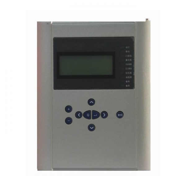
Transformer Protective Relay for 110KV substation
BEPR-830U series digital transformer protection device is complete protection of transformer for 110kV and below voltage levels, providing two harmonic restraint differential protection, switch protection, backup protection fault and reaction phases. The whole device in hardware consists of several independent modules: differential protection unit, the switch quantity protection unit and the backup protection by side configuration unit, each part in the electrical and structure are independent of each other, each side of the backup protection unit at the same time measurement and control function of the side.
The protection device of each electrical protection basic configuration unit is two CPU plug-in, one for protection function unit 32 bit microprocessor, the unit with large capacity RAM and Flash Memory, have extremely strong data processing, logic and information storage capacity; another CPU by bus no chip microcontroller a man-machine interface unit general. Between two CPU plugins are independent of each other, no dependence. A variety of protection and automation functions are realized by the software.
Product Features and Benefits:
- Use high speed processor is the most popular international, frequency is 166 MHz, with abundant resources, the peripheral circuit design is simple, to ensure product quality and stability. Sufficient hardware resources, 4M byte Flash Memory memory, 8M byte SDRAM.
- Measurement of three phase current (Ia, Ib, Ic), three-phase voltage (Uan, Ubn, Ucn), active power P, reactive power of non Q, power factor cos, frequency F.
Maximum of 10 users can input interface custom name. - Protective element can be set by the trip matrix, is convenient for the user to select the relay action. All relay output contact can be selected for the trip contact (automatic) or signal contacts (return after the return).
- With operating loop, adaptive 0.5A~5A switch tripping current.
- When the GPS adopts hard contact pulse pair method.
- Differential protection is to prevent the equipment start or external fault in TA saturation criterion of differential protection malfunction.
- Effective, reliable PT breaking criterion, effectively prevent motor low voltage device malfunction.
- 100M Ethernet communication interface, support for IEC60870-5-103 protocol.
- 9 fault recorders, each record contains the sampling point and the amplitude of wave recording 1.9 seconds, sampling point recorded maximum contains 14 analog (1mS interval), the maximum amplitude wave record contains 40 analog amplitude and 32 switch (5mS interval). Start recording 2 motor (100mS interval), before the start of the 1S, 29S after start of.
- Using the programming technology, graphical and stable reliable protection relay, improve the reliability and validity.
- The static power consumption is low (about 6W), liquid crystal module adopts new technology, greatly increased service life.
- High anti-interference performance, through 10 electromagnetic compatibility testing and certification, the anti-jamming performance of fast transient, electrostatic discharge, surge reached the highest level (IV) standard.
- The working environment temperature range: -25 ℃ ~ +55 ℃ (liquid crystal without fuzzy, slow phenomenon).
Complete protection function configuration
Table 1 Types and functional configuration of this series products
| Function | BEPR-831U | BEPR-832U | |
| Differential relay | √ | ||
| The two harmoin restaint differential | √ | ||
| TA (1) bolt locking differential | √ | ||
| Over current protection | √ | ||
| Negative sequence voltage blocking | √ | ||
| Zero sequence current | √ | ||
| Gap flow | √ | ||
| Clearance overvoltage protection | √ | ||
| Current start fan | √ | ||
| The current blocking voltage | √ | ||
| Overload alarm | |||
| Heavy gas | √ | ||
| Reg . Heavy gas | √ | ||
| Cooler Failure | √ | ||
| Pressure release | √ | ||
| light gas | √ | ||
| Reg . Light gas | √ | ||
| Temp . High | √ | ||
| Telecontrol function pressure plate | √ | ||
| Telemeter | Measurement TA | √ | |
| Protection TA | √ | ||
| Telesignal | √ | √ | |
| Telecontrol | √ | ||
| KWH | Pulse measurement | √ | |
| GPS time-checking | √ | √ | |
| False blocking prevention | √ | √ | |
| Remote management | √ | √ | |
Monitoring
- Telemeter:Ia, Ib, Ic, Ua, Ub, Uc, P, Q, f and other analog telemetry
- Telecontrol:Division and the normal remote control circuit breaker
- Telesignal:16way telesignalling open into the volume of the collection, installation of remote signal deformation, events, letters and other remote
- Remote pulse: 2-way electric-degree pulse input
- Out: Device has a 13 way out, of which 10 road trip because of the export-driven relay, 3-way signal drive for the notice of police.
- GPS time-checking
Technical Parameters
Rated parameters
Rated D.C. voltage : 220V or 110V ( as required )
Rated A. C. data
a) Phase voltage 100 / V
b)Tapped voltage of the line: 100V or 100 /V
c) Rated frequency 50 Hz
Power consumption :
a) D.C circuit normal : not larger than 25W
operation: not larger than 40W
b) A.C voltage circuit not larger than 0.5VA for each phase
c) A.C current circuit not larger than 1VA for each phase (for 5A rating )
not larger than 0.5VA for each phase ( for 1A rating )
Status voltage :
Input voltage to CPU and signal interface 24V (18V~ 30V )
Input voltage to GPS time checking 24V (18V ~ 30V )
Output status (optic coupled output ) permissive voltage 24V ( 18V ~ 30V )
driving power 150 mA
Main technical performance
Operating range for sampling circuits (10% tolerance )
voltage : 0.4V ~120V
current : 0.08In ~ 20In
Contact capacity
current capacity of the signal circuit contact 400VA
arc-breaking capacity of the signal circuit contact 60VA
Tripping and closing current
CB tripping current 0.5A, 1A, 1.5A, 2A, 2.5A, 3A, 3.5A, 4A ( as required )
CB closing current 0.5A, 1A, 1.5A, 2A, 2.5A, 3A, 3.5A, 4A ( as required )
Precision of elements
current elements <± 5%
voltage element <± 5%
synchronism-check angle: <± 1°
timing element <± 20 ms
frequency deviation: <±0.02Hz
slip rated value: <± 5%
Operating Time of the complete protection ( including time needed by relay )
Fixed operating time of the instantaneous zone when measured at 1.2 times of setting value: not longer than 40 ms
Precision of measuring circuits for analog variables monitoring device equipped with the special measurement sub-module :
current, voltage : class 0.2
power, KWH : class 0.5
Insulation property
Insulation resistance
Insulating resistance between active parts and passive parts or casings and electrically unrelated circuits is measured by the 500 megaohmmeter to be not less than 50MΩ for the various circuits at different levels under the normal test atmospheric conditions.
Strength of insulating media
Under the normal test atmospheric conditions, the protection can withstand the power frequency withstand voltage test of 50 Hz, 2000V and 1 min. without any breakdown flashover and element damages. During the test, as a voltage is applied at any tested circuit, the other circuits are inter connected and grounded with an equivalent potential.
Impact voltage
Under the normal test atmospheric conditions, the short-duration impact voltage test of 1.2 /50 µs standard lightning wave is done on the power input circuits. AC input circuits, output contact circuit to the ground and between circuits. The open test voltage is 5 kV.
Heat and moisture-proof performance
The protection can withstand the heat and moisture-proof test stipulated in the Chapter 20, GB/T 7261. The alternating heat and moisture-proof test is to be done at the highest temperature +40ºC, the maximum humidity 95%, for 48 hrs and at a cycle of 24 hrs. In 2 hrs before the test is finished, according to the requirements in section 2.3.1, the insulation resistance between the conducting circuits and external passive metals and casings and electrically unrelated parts are measured to be not less than 1.5 MΩ, the withstand voltage strength of the media not less than 75% of the voltage magnitude of the media strength test stipulated in the section 2.3.2
Electromagnetic compatibility properties
Electrostatic discharge anti-interference
The protection conforms to the standard GB/T17626.2-1998, electrostatic discharge anti-interference test class 4
RF electromagnetic field radiation anti-interference
The protection conforms to the standard GB/T17626.3-1998, RF electromagnetic field radiation anti-interference test class 3
Electric fast transient pulse group anti-interference
The protection conforms to the standard GB/T17626.4-1998, electric fast transient pulse group anti-interference test class 4
Surge(impulse) anti-interference
The protection conforms to the standard GB/T17626.5-1998, surge (impulse) anti-interference test class3
RF field induced conduction interference
The protection conforms to the standard GB/T17626.6-1998, RF field induced conduction interference test class 3
Power frequency magnetic field anti-interference
The protection conforms to the standard GB/T17626.8-1998, Power frequency magnetic field anti-interference test class 5
Pulse magnetic field anti-interference
The protection conforms to the standard GB/T 17616.9-1998, Pulse magnetic field anti-interference test class 5
Damp oscillation magnetic field anti-interference
The protection conforms to the standard GB/T 17626.10, damp oscillation magnetic field anti-interference test class 5
Oscillation wave anti-interference
The protection conforms to the standard GB/T 17626.12-1998, Oscillation wave anti-interference test class 4
Radiated emission value limiting test
The protection conforms to the standard GB9254-1998, radiated emission value limiting test class A
Mechanical performance
Vibration
The protection can withstand the impact duration test of the severity class I stipulated in the section 16.2of GB 7261.
Impact
The protection can withstand the impact duration test of the severity class I stipulated in the section 17.4 of GB 7261.
Crash
The protection can withstand the impact duration test of the severity class I stipulated in the Chapter 18 of GB 7261.
Environment conditions
Ambient temperature :
operation : -20ºC~ +55ºC , less than 35ºC after 24 hours operation
storage : -25ºC ~ +70ºC , no exciting variables are applied at the limit value and no irreversible changes occur. The protection will operate normally after the recovery of temperature.
Relative humidity : maximum monthly average humidity 90 % at the lowest temperature of 25ºC, (no
condensation ). At the highest temperature of +40ºC, maximum humidity must not be
over 50 %.
Atmospheric pressure : 86 ~ 106 kPa ( relative altitude above sea level is less than 2 km ).
Application
110KV Substation and less