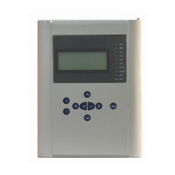
Motor Protective Relay
(For the asynchronous motor of 10KV or less)
BEPR-822U Digital Asynchronous Motor Protection is applicable for 3kV,6kV,10kV non-direct-grounding system serve, as protection for the internal faults, overloadings,etc. of the large and middle asynchronous motors.
The basic configuration of this protection would be two CPU modules, protection and control unit composed of 32-bit microprocessor, which is configured with the bulk RAM and Flash Memory, with strong ability of data processing, logic computation and information storage. Another CPU is the man-machine interface unit composed of single chip computer, whose bus is not out of the chip. The two CUP modules are mutually independent, with no interrelation. Each protection function and automation function would be realized by software.
Product Features:
- All English character LCD display, and clear and easy man-machine interface.
- The precision of the selected measuring modules (including KWH metering ) can reach to the class 0.5.
- To provide access to the accumulated pulse-degree side.
- High speed Ethernet interface is provided to integrated the IEC 870-5-103 standard communication protocol.
- High precision clock chips are used. The GPS time checking circuit is provided to realize the clock synchronism of the whole system.
- High speed Ethernet interface is provided to integrated the IEC 870-5-103 standard communication protocol.
- The core of CPU, the protection functional module is the powerful 32-bit micro- processors with large capacity RAM and Flash Memory. They are powerful to process data, perform logic calculation and store information. 8 to 50 recorded reports and 1000 events can be recorded. These information will not be lost even in power interruption.
Complete protection function configuration
Table 1 Type and function configuration list of these series products
| Function | BEPR-822U | |
| Current instantaneous protection | √ | |
| Over-current protection (definite-time limit or inverse-time limit) | √ | |
| Negative sequence over-current (definite-time limit or inverse-time limit) | √ | |
| Overheat protection | √ | |
| Overload protection | √ | |
| Long-time startup protection | √ | |
| Rotor-locked protection | √ | |
| Fuse protection | √ | |
| F-C locking function | √ | |
| Zero-sequence current protection (trip or alarm) | √ | |
| Under-voltage protection | √ | |
| Over-voltage protection | √ | |
| Zero-sequence over-voltage protection | √ | |
| Non-electric quantity protection | √ | |
|
Two phase differential instantaneous protection |
||
| Two phase current longitudinal differential protection | ||
| Telemeter | Measurement TA | alternative use |
| Protection TA | alternative use | |
| Telesignal | alternative use | |
| Telecontrol | alternative use | |
| KWh | Pulse metering | √ |
| GPS Time synchronization | √ | |
| False-blocking prevention | √ | |
| Remote management | √ | |
Monitoring
- Telemeter:Ia, Ib, Ic, Ua, Ub, Uc, P, Q, f and other analog telemetry
- Telecontrol:Division and the normal remote control circuit breaker
- Telesignal:16way telesignalling open into the volume of the collection, installation of remote signal deformation, events, letters and other remote
- Remote pulse: 2-way electric-degree pulse input
- Out: Device has a 11 way out, of which 8road trip because of the export-driven relay, 3-way signal drive for the notice of police.
- GPS time-checking
Technical Parameters
Rated parameters
Rated DC voltage: 220V or 110V (please specify in the order)
Rated AC data:
a) AC voltage 100 / 3 V
b) AC current 5A or 1A(please specify in the order)
c) Rated frequency 50Hz
Power consumption:
a) DC circuit Under normal work, no more than 8W
During operation, no more than 12W
b)AC voltage circuit No more than 0.5VA for each phase
c)AC current circuit When the rated current is 5A: no more than 1.0VA for each phase.
When the rated current is 1A: no more than 0.5VA for each phase.
Status vector level
The input status vector level of CPU and communication interface module 24V (18 V~30V)CPU output status vector (photo-coupling output) Permitted level 24V(18 V~30V) Driving capability 150Ma
Main technical performance
Sampling circuit precise working range (5% error)
Voltage:0.4 V~120.0V
Current:0.20A~100.0A(When rated current is 5A.)
Zero-sequence current:0.02A~5.50A or 0.1A~20.0A
Contact capacity
Operation circuit contact load: closing capacity 220VDC 5A;
Signal circuit contact load: switching capacity 220VDC 0.15A
Tripping and closing current
CB tripping current 0.5A~5A and above(please specify in the order)
CB closing current 0.5A~5A and above(please specify in the order)
Setting error of each type of component
Current component: ≤±5%
Voltage component: ≤±3%
Time component: ≤(2% setting value)+50ms
Group operation time (including relay inherent time)
Inherent time of fast operation zone: when it is measured at 1.2 times of setting,, no more than 40ms
Inherent time of differential operation: when it is measured at 1.5 times of setting, no more than 30ms
Insulation capability
Insulation resistance
The charged parts and uncharged parts casings, as well as irrelevant electrical circuits are easured by Meg-ohmmeter with open-circuit voltage of 500V, to determine the value of nsulation resistance. Under normal experiment atmospheric condition, each circuit insulation resistance of all levels could not be less than 20MΩ.
Medium intensity
Under normal experiment atmospheric condition, this device can endure frequency of 50Hz, signal input terminal voltage to ground is 500V, and other circuit voltage to ground is 2000V. uring one-minute power frequency voltage withstand test, there is not puncture, flashover and component damage event. During the test, when any testing circuit is energized, all the other circuits are potential interconnected and grounded equipotentially.
Impulse voltage
Under normal experiment atmospheric condition, the power input circuit, AC input circuit, output contact circuit to ground, and all the circuits are able to endure short-time standard lightning impulse voltage test of 1.2/50μs, with open-circuit test voltage of 5kV.
Humidity and heat resistant performance
This device can endure the constant humidity and heat test stipulated in the GB/T 2423.9, with test temperature +40℃±2℃, relative humidity (93±3)%,and test time of 48h. Within two hours after the completion of test, according to the requirements in 2.3.1, among the outside uncharged parts of each conductive circuit, the casing and irrelevant electrical circuits, the insulation resistance is measured, to be not less than 1.5MΩ. The medium voltage withstand intensity is not below the 75% of voltage amplitude in medium intensity test, as stipulated in 2.3.2.
Anti-electromagnetic interference capability
Pulse interference
This device can endure the interference test stipulated in GB/T 14598.13-1998, and the test power frequency is 100kHz and 1MHz, and test voltage is common-mode 2500V, with decaying oscillatory wave of differential mode 1000V. During the test, power is applied to test device in advance; according to critical condition superposed interference test voltage listed in Table 3.1.1 in GB/T 14598.13, there is no maloperation and operation rejection.
Fast Transient interference
This device can endure the (4kV±10%) fast transient interference test of class IV stipulated in GB/T 14598.10-1996 standard.
Static discharge
This device can endure the (space discharge 15kV,contact discharge 8kV) static discharge test of class IV stipulated in GB/T 14598.14-1998 standard.
Radiated electromagnetic Field interference
This device can endure the radiated electromagnetic field interference test severity of class III stipulated in GB/T 14598.9-2002 standard.
Surge
This device can endure the interference test (common mode 2000V,differential mode 1000V), the surge (impact) interference resistance capability test of class III stipulated in GB/T 17626.5-1999 standard.
Mechanical performance
Vibration
This device can endure the vibration response test of severity class I stipulated in 3.2.1 of GB/T 11287-2000. This device can endure the first level grimness vibration duration test regulated in 3.2.2 of GB/T 11287-2000.
Impulse
This device can endure the impulse response test of severity class I stipulated in 4.2.1 of GB/T 14537-1993. This device can endure the first level grimness impact duration test regulated in 4.2.2 of GB/T 14537-1993.
Collision
This device can endure the impulse and collision test of severity class I stipulated in 4.3 of GB/T 14537-1993.
Environmental conditions
a) Environmental temperature:
Work: -10℃~+55℃;-25℃~+70℃(according to contract requirements)
Storage: -25℃~+70℃, if, under limit value, no energized quantities are applied, and the device would not be irreversibly changed. The device can normally operate when the temperature recovers.
b) Relative humidity: 5%~95%((There is no dew or ice inside the product.)
c) Atmospheric pressure: 86kPa~106kPa
Hardware
The demand of reliability is fully considered for overall design and design of each module. In the fields of program execution, signal indication, and communication, elaborate consideration have been given out. Therefore, when the panel-assembly operations for this device are made or when the device is mounted on the switch cabinet, additional AC, DC input anti-interference modules do not need to be installed.
Application
Digital Asynchronous Motor Protection is applicable for 3kV,6kV,10kV non-direct-grounding system serve, as protection for the internal faults, overloadings,etc. of the large and middle asynchronous motors.