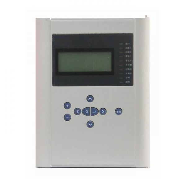
Capacitor Protection Relay For 66KV or smaller substation
BEPR-842U Digital Capacitor Protection Device is a packaged capacitor protection Device that takes the current and voltage protection Device and the unbalance protection Device as its basic configuration and applicable for the capacitor banks of the voltage levels of 66kV or less.
The basic configuration of this protection Device would be two CPU modules, protection and reclosing unit composed of 32-bit microprocessor, which is configured with the bulk RAM and Flash Memory, with strong ability of data processing, logic computation and information storage. Another CPU is the man-machine interface unit composed of single chip computer, whose bus is not out of the chip. The two CPUs modules are mutually independent, with no interrelation.Each protection function and automation function would be realized by software. The logic relation of the protection Device conforms to the standard design principles of the Device.
Features and Benefits:
- All English character LCD display, and clear and easy man-machine interface.
- The precision of the selected measuring modules (including KWH metering ) can reach to the class 0.5.
- To provide access to the accumulated pulse-degree side.
- High speed Ethernet interface is provided to integrated the IEC 870-5-103 standard communication protocol.
- High precision clock chips are used. The GPS time checking circuit is provided to realize the clock synchronism of the whole system.
- High speed Ethernet interface is provided to integrated the IEC 870-5-103 standard communication protocol.
- The core of CPU, the protection functional module is the powerful 32-bit micro- processors with large capacity RAM and Flash Memory. They are powerful to process data, perform logic calculation and store information. 8 to 50 recorded reports and 1000 events can be recorded. These information will not be lost even in power interruption.
- Complete functional configuration
Table 1 Types and functional configuration of this series products
| Function | BEPR-842U | |
| 2-zone inter-phase current | √ | |
| 2-zone zero-sequence current | √ | |
| Current inverse time-limit | √ | |
| Zero-sequence inverse time-limit | √ | |
| Under-voltage protection | √ | |
| Over-voltage protection | √ | |
| Single-phase (3-phase) unbalance voltage | √ | |
| Single-phase (3-phase) unbalance current | ||
| Automatic throw-over / switch-off protection | √ | |
| Telemeter | Measurement level TA | alternative use |
| Protection level TA | alternative use | |
| Telesignal | alternative use | |
| Telecontrol | alternative use | |
| GPS time synchronization | √ | |
| KWh | Pulse metering | √ |
| False-blocking prevention | √ | |
| Remote management | √ | |
Monitoring
- Telemeter: Ia,Ib,Ic,Ua,Ub,Uc, P,Q and other analog telemetry
- Telecontrol:Division and the normal remote control circuit breaker
- Telesignal:16way telesignalling open into the volume of the collection, installation of remote signal deformation, events, letters and other remote
- Remote pulse: 2-way electric-degree pulse input
- Out: Device has a 13 way out, of which 10 road trip because of the export-driven relay, 3-way signal drive for the notice of police.
- GPS time-checking
Technical Parameters
Rated parameters
Rated DC voltage: 220V or 110V (please specify in the order)
Rated AC data:
a) Phase voltage 100 / 3 V
b) Line extract voltage 100 V or 100 / 3 V
c) AC current 5A or1A(Please specify in the order)
c) Rated frequency 50Hz
Power consumption
a) DC power circuit Under normal work: no more than 25W
During operation: no more than 40W
b) AC voltage circuit No more than 0.5VA for each phase
c) AC current circuit
when the rated current is 5A: no more than 1VA for each phase.
when the rated current is 1A: no more than 0.5VA for each phase.
State vector level
The input state variable level of CPU and communication interface module
24V(18 V~30V)
GPS time synchronization impulse input level
24V(18 V~30V)
CPU output state variable (photo-coupling output)
Permissive level 24V(18 V~30V)
Driving capability 150Ma
Main technical performance
Sampling circuit precise working range (10% error)
Voltage:0.4 V~120V
Current:0.08In~20In
Contact capacity
Signal circuit contact load: 400VA
Signal circuit contact arc break: 60VA
Operating circuit contact load: 1100VA (without arc break)
Tripping current and closing current
CIRCUIT BREAKER tripping current 0.5A~4A(please specify in the order)
CIRCUIT BREAKER closing current 0.5A~4A(please specify in the order)
Precision of various components
Current component: ≤±5%
Voltage component : ≤±5%
Time component: ≤±40ms
Complete set operating time (include relay inherent time)
Inherent operation time of transient zone:
≤40ms, measurement is made for 1.2 times of setting
Precision of the analog variable measurement circuit
Monitoring device with the special measurement submodule:
Current, voltage: class 0.2
Power, kWh: class 0.5
Insulation capability
Insulation resistance
The insulation resistance values between the charged parts and in charged parts, racks as well as irrelevant electrical circuits are measured by 500V megger and under normal test atmospheric conditions, the resistance values of the various circuit at all levels are not lower than 50MΩ.
Media intensity
Under normal test atmospheric conditions, the Device can tolerate the frequency 50Hz, signal input terminal to ground voltage, 500V, other circuit to ground voltage 2000V, 1min power-frequency withstand voltage test, without breakdowns, flashovers and element damages. During the test, when the voltage is applied at any tested circuit,all the other circuits are interconnected and grounded equipotentially.
Impulse voltage
Under normal experiment atmospheric conditions, the power input circuit, AC input circuit, output contact point circuit to ground, and all the circuits are able to endure short-time standard lightning impulse voltage test of 1.2/50μs, with open-circuit test voltage of 5kV.
Humidity and heat resistance performance
This Device can endure the constant humidity and heat test regulated in GB/T 7261-2000, chapter 20, with highest test temperature +40℃, hightest humidity 95%,and test time of 48h. Within two hours after the completion of test, according to the requirements in 2.3.1, among the outside uncharged parts of each conductive circuit, the casing and irrelevant electrical circuits, the insulation resistance is measured, and it is no less than 1.5MΩ. The medium voltage withstand intensity is not below the 75 % of voltage amplitude in medium intensity test, as regulated in 2.3.2.
Humidity and heat resistance performance
Electromagnetic compatibility (EMC) capability
Electrostatic discharge immunity test
This Device can endure the electrostatic discharge immunity test Class IV stipulated in GB/T 17626.2-1998.
Radiated Radio-frequency electromagnetic field immunity test
This Device can endure the radiated, radio-frequency, electromagnetic field immunity test Class III stipulated in GB/T 17626.3-1998.
Electrical fast transient/burst immunity
This Device can endure the electrical fast transient/burst immunity test Class IV stipulated in GB/T 17626.4-1998.
Surge immunity test
This Device can endure the surge immunity test Class III stipulated in GB/T 17626.5-1999.
Immunity to conducted disturbances, induced by radio-frequency fields
This Device can endure the immunity to conducted disturbances, induced by radio-frequency fields test Class III stipulated in GB/T 17626.6-1998.
Power frequency magnetic field immunity test
This Device can endure the power frequency magnetic field immunity test Class V stipulated in GB/T 17626.8-1998.
Pulse magnetic field immunity test
This Device can endure the pulse magnetic field immunity test regulated Class
V stipulated in GB/T 17626.9-1998.
Damped oscillatory magnetic field immunity test
This Device can endure the damped oscillatory magnetic field immunity test Class V stipulated in GB/T 17626.10-1998.
Oscillatory waves immunity test
This Device can endure the oscillatory waves immunity test Class IV stipulated in GB/T 17626.12-1998.
Radiated emission limited value test
This Device has passed the radiated emission limited value test A stipulated in GB 9254-1998